Modulation with Pulse Shaping and Filtering Examples
Rectangular Pulse Shaping
Rectangular pulse shaping repeats each output from the modulator a fixed number of times to create an upsampled signal. Although it is less realistic than other kinds of pulse shaping, rectangular pulse shaping can be a first step or an exploratory step in algorithm development. If the transmitter upsamples the modulated signal, then the receiver should downsample the received signal before demodulating. This code uses the rectpulse function for rectangular pulse shaping at the transmitter and the intdump function for downsampling at the receiver. The integrate and dump operation is one way to downsample the received signal.
Define simulation variables and create a random digital message.
M = 16;                     % Alphabet size, 16-QAM
Nsamp = 4;                  % Oversampling rate
snr = 15;                   % Signal to noise ratio in dB
x = randi([0 M-1],5000,1);  % Message signal
Apply 16-QAM modulation and rectangular pulse shaping. Transmit the signal through an AWGN channel.
y = qammod(x,M);
ypulse = rectpulse(y,Nsamp);
ynoisy = awgn(ypulse,15,'measured');
Downsample at the receiver. Use a spectrumAnalyzer to compare the pulse-shaped transmitted signal before and after the addition of AWGN.
ydownsamp = intdump(ynoisy,Nsamp);
sa1 = spectrumAnalyzer( ...
    Title="16-QAM Signal with Rectangular Pulse Shaping", ...
    ChannelNames={'No noise','SNR=15 dB'});
sa1(ypulse,ynoisy)

Demodulate to recover the message.
z = qamdemod(ydownsamp,M);
Pulse Shaping Using Raised Cosine Filter System Objects
Filter a 16-QAM signal using a pair of square root raised cosine matched filters. Plot the eye diagram and scatter plot of the signal. After passing the signal through an AWGN channel, calculate the number of bit errors.
Set the simulation and filter parameters.
M = 16;         % Modulation order
bps = log2(M);  % Bits per symbol
n = 20000;      % Transmitted bits
sps = 4;        % Samples per symbol
EbNo = 10;      % Eb/N0 (dB)
span = 10;      % Filter span in symbols
rolloff = 0.25; % Filter rolloff factor
Create the raised cosine transmit and receive filter objects using the defined parameters.
txfilter = comm.RaisedCosineTransmitFilter( ...
    RolloffFactor=rolloff, ...
    FilterSpanInSymbols=span, ...
    OutputSamplesPerSymbol=sps);

rxfilter = comm.RaisedCosineReceiveFilter( ...
    RolloffFactor=rolloff, ...
    FilterSpanInSymbols=span, ...
    InputSamplesPerSymbol=sps, ...
    DecimationFactor=sps);
Plot the impulse response of the raised cosine transmit filter object txFilter.
impz(txfilter.coeffs.Numerator)
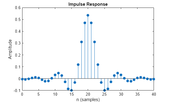
Calculate the delay through the matched filters. The group delay is half of the filter span through one filter and is, therefore, equal to the filter span for both filters. Multiply by the number of bits per symbol to get the delay in bits.
filtDelay = bps*span;
Create an error rate counter System object™. Set the ReceiveDelay property to account for the delay through the matched filters.
errorRate = comm.ErrorRate(ReceiveDelay=filtDelay);
Generate binary data.
x = randi([0 1],n,1);
Modulate the data.
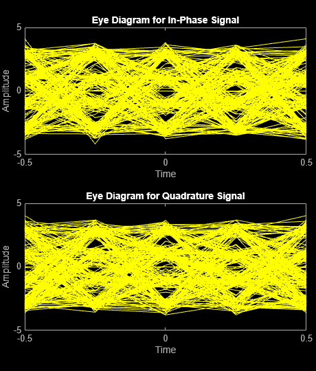
modSig = qammod(x,M,InputType="bit");Filter the modulated signal, and then plot the eye diagram of the first 1000 samples.
txSig = txfilter(modSig);
eyediagram(txSig(1:1000),sps)
Calculate the signal-to-noise ratio (SNR) in dB given . Pass the transmitted signal through the AWGN channel using the awgn function.
SNR = convertSNR(EbNo,"ebno","snr", ...
    SamplesPerSymbol=sps, ...
    BitsPerSymbol=bps);
noisySig = awgn(txSig,SNR,"measured");
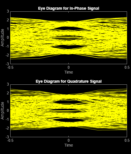
Filter the noisy signal, and then display its eye diagram and scatter plot.
rxSig = rxfilter(noisySig);
eyediagram(rxSig(1:1000),sps)
scatterplot(rxSig)

Demodulate the filtered signal and calculate the error statistics. The delay through the filters is accounted for by the ReceiveDelay property in errorRate.
z = qamdemod(rxSig,M,OutputType="bit");

errStat = errorRate(x,z);
fprintf('\nBER = %5.2e\nBit Errors = %d\nBits Transmitted = %d\n',...
    errStat)
BER = 1.15e-03
Bit Errors = 23
Bits Transmitted = 19960
nzmod = awgn(modSig,SNR,"measured");
demodsig = qamdemod(nzmod,M,OutputType="bit");
errorRate2 = comm.ErrorRate;
errStat2 = errorRate2(x,demodsig);
fprintf('\nBER = %5.2e\nBit Errors = %d\nBits Transmitted = %d\n',...
    errStat2)
BER = 5.86e-02
Bit Errors = 1172
Bits Transmitted = 20000