PM Demodulator Passband
Demodulate PM-modulated data
Libraries:
Communications Toolbox /
Modulation /
Analog Passband Modulation
Description
The PM Demodulator Passband block demodulates a signal that was modulated using phase modulation. The input is a passband representation of the modulated signal. Both the input and output signals are real scalar signals.
Examples
Sample a 100 Hz linear frequency sweep chirp with a 400 Hz target frequency at 4 kilosamples per second. Modulate the input signal using the phas modulation method. Demodulate the signal. Plot the input signal, the modulated signal, and the demodulated signal.
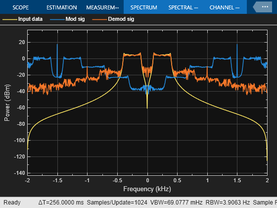
The pmmoddemod_passband model modulates the input linear frequency sweep chirp signal using the PM method at a carrier frequency of 1.5 kHz with pi/2 phase deviation and then demodulates the signal. When the model runs, it plots the signals. This configuration ensures the Hilbert transform filter operates in the flat section of the magnitude response and that the demodulated signal has the desired magnitude and form.

The spectrum analyzer plot shows input signal, the modulated signal, and the demodulated signal.
Limitations
This block does not work inside a triggered subsystem.
Ports
Input
Output
Parameters
Block Characteristics
Data Types |
|
Multidimensional Signals |
|
Variable-Size Signals |
|
More About
To design the Hilbert transform filter, this block uses the Analytic Signal block, which computes the complex analytic signal corresponding to each channel of the real M-by-N input, u
where and denotes the Hilbert transform. The real part of the output in each channel is a replica of the real input in that channel. The imaginary part is the Hilbert transform of the input. In the frequency domain, the analytic signal retains the positive frequency content of the original signal while zeroing-out negative frequencies and doubling the DC component.
The block computes the Hilbert transform using an equiripple FIR filter with the order that you specify using the Hilbert Transform filter order (must be even) parameter, n. This linear phase filter uses the Remez exchange algorithm and imposes a delay of n/2 on the input samples.
Because the block uses this filter, it requires a carrier frequency that exceeds the sample rate of the input signal by at least 10%.
For example, this plot shows the response for a 10 Hz input signal at 8000 samples per second passed through a Hilbert transform filter of order 100.
A carrier frequency that is 10% to 90% higher than the sample rate of the input signal, ensures that the Hilbert transform filter operates in the flat section of its magnitude response (shown in blue) and that the modulated signal has the desired magnitude and form.
Extended Capabilities
Version History
Introduced before R2006a