Pluto Transmitter
Transmit data to Analog Devices ADALM-PLUTO radio
Add-On Required: This feature requires the Communications Toolbox Support Package for Analog Devices ADALM-Pluto Radio add-on.
Libraries:
Communications Toolbox Support Package for ADALM-PLUTO Radio
Description
The Pluto Transmitter block is a signal source that sends data to an Analog Devices® ADALM-PLUTO radio. This connection enables you to simulate and develop various SDR applications.
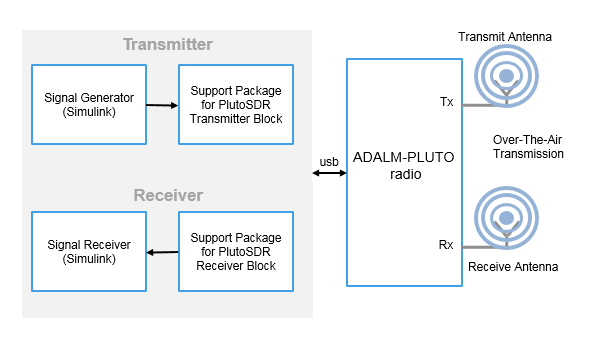
The following diagram shows the interaction between Simulink®, the Pluto Transmitter block, and the radio hardware.

If the host is not connected to radio hardware, you can still use this block to develop a model that propagates sample time and data type information. To propagate this information, update your diagram.
Channel Input
The ADALM-PLUTO radio has a single channel for transmitting data from the Pluto Transmitter block. The block accepts a column vector signal of fixed length.
When the Pluto Transmitter block is called during simulation, it is possible
that the host did not send valid data to the radio hardware. To determine when valid data is
present, use the underflow port.
Design Custom Filter
If the gain or bandwidth characteristics of the default filter does not satisfy the requirements for your application, use the ADI filter wizard to design a custom filter that meets your specific requirements.
By using the ADI filter wizard, you can change the default filter design applied to the filter chain in the Pluto Transmitter block. To open the filter wizard, on the Advanced tab of the block, click Design custom filter. The wizard enables you to design a custom filter for the Analog Devices AD9361/AD9364 RF chip based on the Baseband sample rate (Hz) parameter. You can adjust and optimize the settings for calculating the analog filters, the interpolation and decimation filters, and the FIR coefficients. When you finish with the wizard, to apply the filter settings, click Apply on the block.
The ADI filter wizard requires the following MathWorks® products:
MATLAB®
Signal Processing Toolbox™
DSP System Toolbox™
For instructions on operating the ADI filter wizard, visit the Analog Devices website at MATLAB Filter Design Wizard for AD9361.
For more information, see Baseband Sampling Rate and Filter Chains.
Examples
Ports
Input
Output
Parameters
Version History
Introduced in R2017a


