Generate Drive Cycles for Real Driving Emissions
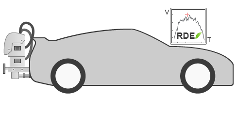
Real Driving Emissions (RDE) is an emissions standard required by the European Union. To meet this standard, a car is driven on public roads and over a wide range of different conditions. Specific equipment installed on the vehicle, the portable emission measuring system (PEMS), collects data to verify that legislative caps for pollutants such as nitrogen oxides (NOx) are not exceeded.
This example shows how to generate an RDE-compliant trip using MATLAB.
Set RDE Trip Parameters
Instantiate an RDE object.
DriveCycles = RDE.DriveCycles; % create RDE objectSet the ampling interval, in s.
DriveCycles.dt = 1; % sampling interval [s]Set the velocity threshold for the stop condition, in m/s.
DriveCycles.StopSpeedTh = 1/3.6; % stop velocity threshold [m/s]RDE Trip Specifications
RDE trips cover three types of operation: urban, rural, and motorway. All data sets with v ≤ 60 km/h belong to the urban speed bin category. All data sets with 60 km/h < v ≤ 90 km/h belong to the rural speed category. All data sets with v > 90 km/h belong to the motorway speed category. These classifications are based purely on speed. Based on the speed definition, time should be evenly distributed for each category within a 10% tolerance. The table shows the distance and speed specifications for each urban, rural, and motorway part of the RDE test.
Trip Details | Provision Set in Legal Text |
|---|---|
Duration | Between 90 and 120 min |
Distance | |
Urban | > 16 km |
Rural | > 16 km |
Motorway | > 16 km |
Composition | |
Urban | 29% to 44% of distance |
Rural | 23% to 43% of distance |
Motorway | 23% to 43% of distance |
Average speeds | |
Urban | 15 to 40 km/h |
Rural | Between 60 and 90 km/h |
Motorway | > 90 km/r >100 km/h for at least 5 min |
Boundary Conditions for RDE Tests
In addition to specifying the trip characterization, other defined boundary conditions include ambient conditions, stop times, maximum speed, and altitude. A set of additional dynamic boundary conditions has been added for the second RDE legislative package to exclude driving that can be regarded as too smooth or too aggressive, based on indicators such as speed and acceleration. The present RDE package does not generate altitude or temperature data.
The table shows the dynamic boundary conditions for the RDE tests.
Parameter | Provision Set in Legal Text |
|---|---|
Payload | Less than or equal to 90% of maximum vehicle weight |
Altitude | |
Moderate | 0 to 700 m |
Extended | Between 700 m and 1300 m |
Altitude difference | No more than a 100 m altitude difference between start and finish |
Cumulative altitude gain | 1200 m/100 km |
Ambient temperature | |
Moderate | 0°C to 30°C |
Extended | From -7°C to 0°C and 30°C to 35°C |
Stop percentage | Beteen 6% and 30% of urban time |
Maximum speed | 145 km/h (160 km/hr for 3% of motorway driving time) |
Rural | 23% to 43% of distance |
Motorway | 23% to 43% of distance |
Dynamic boundary conditions | |
Maximum metric (defined in 4.1.1) | 95th percentile of v*a (speed * positive accleration) for each trip segment (urban, rural, motorway) |
Minimum metric (defined in 4.1.2) | Relative positive acceleration (RPA) for each trip segment (urban, rural, motorway) |
RDE Parameters
Set the velocity range, in m/s, across urban, rural, and motorway operation. This parameter is defined in the RDE legislation in sections 6.3.1, 6.4.1, 6.4.2, and 6.5.1.
DriveCycles.OperationModeBoundaries = [60 90]/3.6; % Boundaries between urban, rural, motorway [m/s]Set the allowed distance normalized percentage for the urban part of the trip. This parameter is defined in the RDE legislation in section 6.6.1.
DriveCycles.UrbanRatioRange = [0.29 0.44]; % Allowed distance normalized percentage for the urban part of the trip []Set the allowed distance normalized percentage for the rural part of the trip. This parameter defined in the RDE legislation in section 6.6.2.
DriveCycles.RuralRatioRange = [0.23 0.43]; % Allowed distance normalized percentage for the rural part of the trip []Set the allowed distance normalized percentage for the motorway part of the trip. This parameter is defined in the RDE legislation in section 6.6.3.
DriveCycles.MotorwayRatioRange = [0.23 0.43]; % Allowed distance normalized percentage for the motorway part of the trip []Set the usual max velocity, in m/s. Ths value can be occasionally higher, such as when overpassing. This parameter is defined in the RDE legislation in section 6.7.1.
DriveCycles.MotorwayUsualMaxSpeed = 145/3.6; % Usual max velocity [m/s] (can be occasionally higher, for overpassing, etc.)Set the time ratio limit for higher velocities.
DriveCycles.MotorwayAbsoluteSpeedTimeRatio = 0.03; % Time ratio limit for higher velocities []Set the absolute max velocity, in m/s.
DriveCycles.MotorwayAbsoluteMaxSpeed = 160/3.6; % Absolute max velocity [m/s] (cannot be higher than this)Set the urban allowed speed range. This parameter is defined in the RDE legislation in section 6.8.1.
DriveCycles.UrbanAverageSpeedRange = [15 40]/3.6; % urban allowed speed range [m/s]Set the urban stop normalized percentage range. This parameter is defined in the RDE legislation in section 6.8.2.
DriveCycles.UrbanStopRatioRange = [0.06 0.3]; % Urban stop normalized percentage range []Set the urban min stop time and number of stop events.These parameters are defined in the RDE legislation in section 6.8.3.
DriveCycles.UrbanMinStopTime = 10; % Urban min stop time [s]
DriveCycles.UrbanMinStopCount = 2; % Urban min stop occurrences []
Set the motorway min velocity and time allowed for min velocity. These parameters are defined in the RDE legislation in section 6.9.1.
DriveCycles.MotorwayUsualMinSpeed = 100/3.6; % Motorway min velocity [m/s]
DriveCycles.MotorwayUsualMinSpeedTime = 5*60; % Time allowed for min velocity [s]
Set the range for RDE trip duration. This parameter is defined in the RDE legislation in section 6.10.1.
DriveCycles.TripDurationRange = [90 120]*60; % Allowed total trip duration range [s]Set the min distance for urban, rural, and motorway parts of the trip. These parameters are defined in the RDE legislation in section 6.12.
DriveCycles.UrbanMinDistance = 16000; % Min distance for urban part [m]
DriveCycles.RuralMinDistance = 16000; % Min distance for rural part [m]
DriveCycles.MotorwayMinDistance = 16000; % Min distance for motorway part [m]
Set the rural and motorway average speed ranges.
DriveCycles.RuralAverageSpeedRange = [60 90]/3.6; % Rural average speed range [m/s]
DriveCycles.MotorwayAverageSpeedRange = [90 145]/3.6; % Motorway average speed range [m/s]
Dynamic Boundary Conditions Used by the Relative Positive Acceleration (RPA) and VA95
These conditions are defined to exclude driving that could be regarded as too smooth or too aggressive, based on indicators such as speed and acceleration.
To be valid, each urban, rural, and motorway section of an RDE trip must be below the VA95 constraint line and above the RPA constraint line.


RPA has units of m/s^2 or kWs/(kg*km). Values greater than 0.1 m/s^2 indicate positive acceleration.
VA95 is the 95th percentile of the product of vehicle speed per positive acceleration greater than 0.1 m/s^2 and has units of m^2/s^3 or W/kg, similar to a power to mass ratio.
Parameters for VA95 Indicator Verification
These parameters are defined in the RDE legislation in section 4.1.1.
DriveCycles.VA95VelocityThreshold = 74.6/3.6; % m/s
DriveCycles.VA95BoundarySpeedCoeff1 = 0.136; % units equivalent to m/s^2
DriveCycles.VA95BoundaryBias1  = 14.44; %W/kg
DriveCycles.VA95BoundarySpeedCoeff2 = 0.0742; % units equivalent to m/s^2
DriveCycles.VA95BoundaryBias2  = 18.966; % W/kg
Parameters for RPA Verification
These parameters are defined in the RDE legislation in section 4.1.2.
DriveCycles.RPAVelocityThreshold = 94.05/3.6; % m/s
DriveCycles.RPABoundarySpeedCoeff = -0.0016; % units equivalent to 1/s
DriveCycles.RPABoundaryBias = 0.1755; % m/s^2
DriveCycles.RPALowerBound = 0.025; % m/s^2
RDE Generator Parameters
Set these parameters for RDE generation.
DriveCycles.ShapeParameter = 1; % Velocity generator uses the gamma PDF and this is the PDF's tuning parameter DriveCycles.SmoothingMethod ='loess'; % velocity using MATLAB smooth function DriveCycles.SmoothingWindowLength = 5; % window length
Set the number of RDE trips to be generated.
DriveCycles.NTrips = 4; % number of RDE tripsSet the number attempts to generate a valid RDE trip.
DriveCycles.NumberOfIterations = 10000; % iteration find valid trip limitSet the output folder for RDE data.
DriveCycles.OutputFolder = fullfile(pwd(), 'results'); % output folder location
Generate RDE Trips
To generate RDE trips, use this command. This command also saves the timeseries data as separate CSV files.
DriveCycles.generateDriveCycles(); % generated the results RDE compliant drive cycle successfully generated in 81 iterations RDE compliant drive cycle successfully generated in 92 iterations RDE compliant drive cycle successfully generated in 33 iterations RDE compliant drive cycle successfully generated in 120 iterations
To view and check the drive cycle files, open the files using an application available on your platform. For example, on the Windows® platform, use the command winopen("./results/drive_cycle_1.csv").
Plot the Generated RDE Trips
DriveCycles.plotDriveCycles % plot the results 
RDE Legislative Packages
The RDE legislation is divided into four packages that cover various areas such as specifications for measurement equipment, trip definitions, and boundary conditions.
RDE Package 1 — Basic features of the RDE test, such as characterization of the RDE trip, the vehicle family concept, description of the data evaluation tools, technical requirement of the PEMS equipment, and reporting obligations. See Commission Regulation (EU) 2016/427 in Official Journal of the European Union, L81/2, March 31, 2016.
RDE Package 2 — Determination of the conformity factors and the timetable for RDE implementation. Technical features include the introduction of dynamic boundary conditions and a limit for altitude gain together with a detailed approach to calculating it. See Commission Regulation (EU) 2016/646 in Official Journal of the European Union, L 109, April 26, 2016.
RDE Package 3 — Particulate number measurement, provisions for hybrids, and a procedure to include cold starts and regeneration events in the RDE test. See Commission Regulation (EU) 2017/1151 in Official Journal of the European Union, L 175, July 7, 2017.
RDE Package 4 — In-service compliance and surveillance tests along with specific provisions for light commercial vehicles (vans). See Commission Regulation (EU) 2018/1832 in Official Journal of the European Union, L 301, November 27, 2018.
See Also
Related Topics
You can also select a web site from the following list
Americas
- América Latina (Español)
- Canada (English)
- United States (English)
Europe
- Belgium (English)
- Denmark (English)
- Deutschland (Deutsch)
- España (Español)
- Finland (English)
- France (Français)
- Ireland (English)
- Italia (Italiano)
- Luxembourg (English)
- Netherlands (English)
- Norway (English)
- Österreich (Deutsch)
- Portugal (English)
- Sweden (English)
- Switzerland
- United Kingdom (English)
Asia Pacific
- Australia (English)
- India (English)
- New Zealand (English)
- 中国
- 日本Japanese (日本語)
- 한국Korean (한국어)