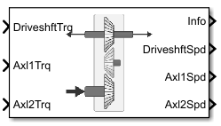
Transfer Case
Libraries:
Powertrain Blockset /
Drivetrain /
Final Drive Unit
Vehicle Dynamics Blockset /
Powertrain /
Drivetrain /
Final Drive Unit
Description
The Transfer Case block implements a differential as a planetary bevel gear train. The block matches the driveshaft bevel gear to the crown (ring) bevel gear. You can specify:
Carrier-to-driveshaft ratio
Crown wheel location
Viscous and damping coefficients for the axles and carrier
Use the Transfer Case block to:
Dynamically couple the post-transmission driveshaft to the wheel axles or universal joints
Model simplified or older drivetrains when optimal traction control does not require passive or active torque vectoring
Model mechanical power splitting in generic gearbox and drive line scenarios
The block is suitable for use in hardware-in-the-loop (HIL) and optimization workflows. All the parameters are tunable.
Efficiency
To account for the block efficiency, use the Efficiency factors parameter. This table summarizes the block implementation for each setting.
| Setting | Implementation |
|---|---|
| Constant efficiency that you can set with the Constant efficiency factor, eta parameter. |
| Efficiency as a function of base gear input torque, air temperature, and driveshaft speed. Use these parameters to specify the lookup table and breakpoints:
For the air temperature, you can either:
To select the interpolation method, use the Interpolation method parameter. For more information, see Interpolation Methods. |
Power Accounting
For the power accounting, the block implements these equations.
| Bus Signal | Description | Equations | ||
|---|---|---|---|---|
|
|
| Mechanical power from driveshaft | |
| Mechanical power from axle 1 | |||
| Mechanical power from axle 2 | |||
|
|
| Total power loss | ||
| Power loss due to damping | |||
|
|
| Rate change of stored internal energy | ||
Dynamics
The Transfer Case block implements these differential equations to represent the mechanical dynamic response for the crown gear, front axle, and rear axle.
| Mechanical Dynamic Response | Differential Equation |
|---|---|
| Crown Gear |
|
| Front Axle |
|
| Rear Axle |
|
The equations use these variables.
| N | Carrier-to-driveshaft gear ratio |
| Jd | Rotational inertia of the crown gear assembly |
| bd | Crown gear linear viscous damping |
| ωd | Driveshaft angular speed |
| η | Differential efficiency |
| J1 | Axle 1 rotational inertia |
| b1 | Axle 1 linear viscous damping |
| ω1 | Axle 1 speed |
| J2 | Axle 2 rotational inertia |
| b2 | Axle 2 linear viscous damping |
| ω2 | Axle 2 angular speed |
| Td | Driveshaft torque |
| T1 | Axle 1 torque |
| T2 | Axle 2 torque |
| Ti | Driveshaft internal resistance torque |
| Ti1 | Axle 1 internal resistance torque |
| Ti2 | Axle 2 internal resistance torque |
Ports
Inputs
Output
Parameters
Extended Capabilities
Version History
Introduced in R2021b
