Equivalent Circuit Battery
Resistor-capacitor (RC) circuit battery
Libraries:
Powertrain Blockset /
Energy Storage and Auxiliary Drive /
Network Battery
Description
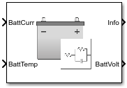
The Equivalent Circuit Battery block implements a resistor-capacitor (RC) circuit battery that you can parameterize using equivalent circuit modeling (ECM). To simulate the state-of-charge (SOC) and terminal voltage, the block uses load current and internal core temperature.
The Equivalent Circuit Battery block calculates the combined voltage of the network battery using parameter lookup tables. The tables are functions of the SOC and battery temperature. You can use the Estimation Equivalent Circuit Battery block to help create the lookup tables.
Specifically, the Equivalent Circuit Battery block implements these parameters as lookup tables that are functions of the SOC and battery temperature:
Series resistance, Ro=ƒ(SOC,T)
Battery open-circuit voltage, Em=ƒ(SOC,T)
Battery capacity, Cbatt=ƒ(T)
Network resistance, Rn=ƒ(SOC,T)
Network capacitance, Cn=ƒ(SOC,T)
To calculate the combined voltage of the battery network, the block uses these equations.
Positive current indicates battery discharge. Negative current indicates battery charge.
Power Accounting
For the power accounting, the block implements these equations.
| Bus Signal | Description | Equations | ||
|---|---|---|---|---|
|
|
| Battery network power | |
|
|
| Battery network power loss | ||
|
|
| Battery network power stored | ||
The equations use these variables.
SOC | State-of-charge |
Em | Battery open-circuit voltage |
Ibatt | Per module battery current |
Iin | Combined current flowing from the battery network |
Ro | Series resistance |
Np | Number parallel branches |
Np | Number of RC pairs in series |
Vout, VT | Combined voltage of the battery network |
Vn | Voltage for |
Rn | Resistance for |
Cn | Capacitance for |
Cbatt | Battery capacity |
Pbatt | Battery power |
PLossBatt | Negative of battery network power loss |
PBattLoss | Battery network power loss |
PStoredBatt | Battery network power stored |
PLdBatt | Battery network power |
T | Battery temperature |
Current Polarity, Hysteresis, and Entropic Heating
To incorporate current polarity, hysteresis voltage, and entropic heating into the battery model, enable these block parameters:
Include current polarity
Include hysteresis
Include entropic heating
To improve calibration for charging and discharging processes, select Include current polarity. To model the current polarity, the block implements resistive and capacitive lookup tables with current direction.
Hysteresis voltage adds a state estimator for non-linear voltage offsets when the battery current changes from charge to discharge. To calculate the combined voltage of the battery network with hysteresis, select Include hysteresis. The block uses these equations.
Entropic heating accounts for power losses that occur during the battery phase change. To calculate the battery network power loss with entropic heating, select Include entropic heating. The block uses these equations.
The equations use these variables.
Hstate | Hysteresis state variable |
HystRate | Hysteresis rate |
VHyst | Hysteresis voltage |
MaxHystVolt | Maximum hysteresis voltage |
InstHystVolt | Instantaneous hysteresis voltage |
EntdUdT | Entropic coefficient |
Pentropic | Entropic reversible losses |
Examples

Build Full Electric Vehicle Model
Build a vehicle with a motor-generator, battery, direct-drive transmission, and powertrain control algorithms using the electric vehicle (EV) reference application.
Ports
Inputs
Output
Parameters
References
[1] Ahmed, Ryan, et al. "Model-Based Parameter Identification of Healthy and Aged Li-ion Batteries for Electric Vehicle Applications." SAE International Journal of Alternative Powertrains. 4, no. 2 (2015): 233 -47. https://doi.org/10.4271/2015-01-0252.
[2] Gazzarri, Javier, Nishant Shrivastava, Robyn Jackey, and Craig Borghesani. "Battery Pack Modeling, Simulation, and Deployment on a Multicore Real Time Target." SAE International Journal of Aerospace. 7, no. 2 (2014): 207–13. https://doi.org/10.4271/2014-01-2217.
[3] Huria, Tarun, Massimo Ceraolo, Javier Gazzarri, and Robyn Jackey. “High Fidelity Electrical Model with Thermal Dependence for Characterization and Simulation of High Power Lithium Battery Cells.” IEEE® International Electric Vehicle Conference, March 2012. https://doi.org/10.1109/ievc.2012.6183271.
[4] Huria, Tarun, Massimo Ceraolo, Javier Gazzarri, and Robyn Jackey. "Simplified Extended Kalman Filter Observer for SOC Estimation of Commercial Power-Oriented LFP Lithium Battery Cells." SAE Technical Paper Series, 2013. https://doi.org/10.4271/2013-01-1544.
[5] Jackey, Robyn A. "A Simple, Effective Lead-Acid Battery Modeling Process for Electrical System Component Selection." SAE Technical Paper Series, 2007. https://doi.org/10.4271/2007-01-0778.
[6] Jackey, Robyn A., Gregory L. Plett, and Martin J. Klein. "Parameterization of a Battery Simulation Model Using Numerical Optimization Methods." SAE Technical Paper Series, 2009. https://doi.org/10.4271/2009-01-1381.
[7] Jackey,Robyn, et al. "Battery Model Parameter Estimation Using a Layered Technique: An Example Using a Lithium Iron Phosphate Cell." SAE Technical Paper Series, 2013. https://doi.org/10.4271/2013-01-1547.
[8] Geng, Zeyang, Jens Groot, and Torbjorn Thiringer. “A Time- and Cost-Effective Method for Entropic Coefficient Determination of a Large Commercial Battery Cell.” IEEE Transactions on Transportation Electrification 6, no. 1 (March 2020): 257–66. https://doi.org/10.1109/TTE.2020.2971454.
Extended Capabilities
Version History
Introduced in R2017aSee Also
Datasheet Battery | Estimation Equivalent Circuit Battery
Topics
- Generate Parameter Data for Equivalent Circuit Battery Block
- Characterize Powertrain Blockset and Simscape Battery Blocks (App) (Model-Based Calibration Toolbox)