Subarrays in Large Finite Array for Hybrid Beamforming
This example shows how to design subarrays in large finite array for hybrid beam forming. Hybrid beamforming combines analog beamforming with digital precoding to intelligently form the patterns transmitted from a large antenna array.
Array Parameters
Choose number of elements, frequency of operation and the azimuth and elevation angle to steer the main beam of the array.
N = 11;
fc = 28e9;
az = 30;
el = 20;
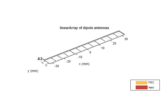
Find Phase Shifts for Azimuth Control
Design a linear array at the desired frequency. The default element is a dipole. Find the phase shifts to apply on each element of the linear array for controlling the main beam in the azimuthal direction. Note, that the distance of separation is chosen to be half-wavelength to ensure no grating lobes.
l = design(linearArray,fc);
elem = l.Element;
elem.Tilt = 90;
l.NumElements = N;
figure
show(l)
ps_az = phaseShift(l,fc,[az;0]);
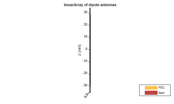
Find Phase Shifts for Elevation Control
Compute the phase shifts for the steering in elevation. To do this, we modify the geometry of our initial linear array for the echelon configuration along z.
elem.Tilt = 90;
elem.TiltAxis = [0 1 0];
l.Tilt = 90;
l.TiltAxis = [0 1 0];
l.ElementSpacing = 1.05*(elem.Length) ;
figure
show(l)
ps_el = phaseShift(l,fc,[0;el]);
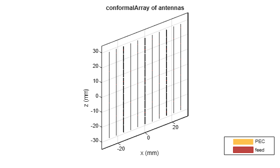
Create Subarrays
Create a N-by-N rectangular array comprising of N, 1-by-N linear arrays stacked along the positive and negative z-directions.
l.Tilt = 0;
elem.Tilt = 0;
l.PhaseShift = ps_az;
c = conformalArray;
zposn = fliplr((-N+1)/2:1:(N-1)/2);
for i = 1:N
   c.Element{i} = l;
   c.ElementPosition(i,:) = [0,0,zposn(i)*l.ElementSpacing];
end
figure
show(c)
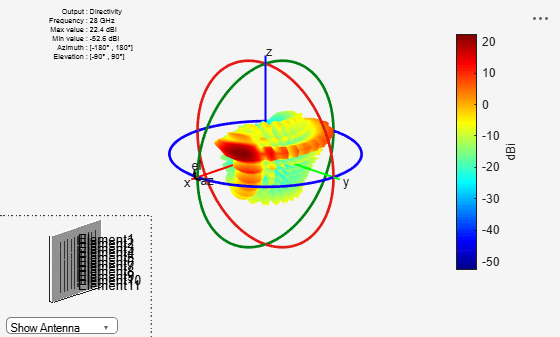
Assign Phase Shifts and Plot Pattern
Assign the sub-array level phase shifts and compute pattern
c.PhaseShift = ps_el;
figure
pattern(c,fc);
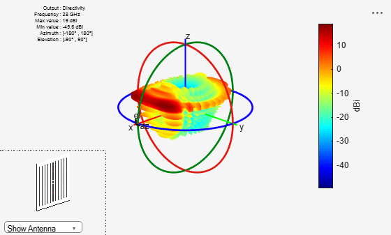
figure
patternElevation(c,fc,az);
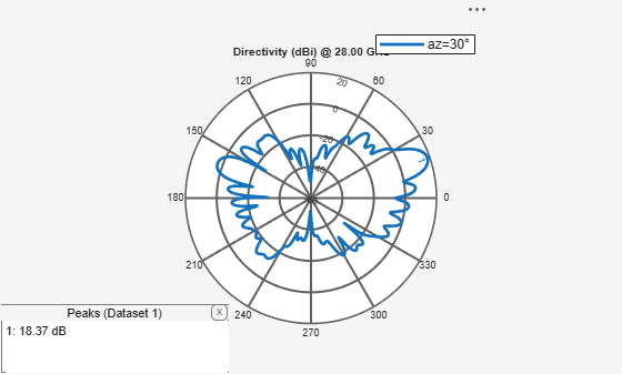
Note that the actual peak location varies from the theoretical computed due to mutual coupling.
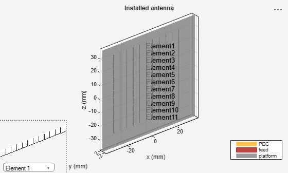
Array with Large Reflector Backing
Using the installed antenna capability, allows for an initial approximate analysis of the antenna array by including a large structure in its vicinity. For this example provide an STL file of a large metallic reflector positioned a quarter-wavelength away from the array. The analysis treats the array using a full-wave Method of Moments (MoM) approach and the large reflector is handled using the Physical Optics (PO) approximation.
lambda = physconst("lightspeed")/fc;
ref_offset = lambda/4;
p = platform;
p.FileName = "GroundPlane.stl";
p.Units = "m";
p.Tilt = 90;
f = installedAntenna;
f.Platform = p;
f.Element = c.Element;
f.ElementPosition = c.ElementPosition;
f.ElementPosition(:,2) = ref_offset;
f.FeedPhase = ps_el;
figure
show(f)
Approximate Array Pattern
figure
pattern(f,fc)