Radar Cross Section Benchmarking
This example performs benchmarking of the Radar Cross Section (RCS) computation on three structures: a square plate, a circular plate and the NASA almond. The benchmarking for the square and circular plate is done against the analytical physical optics based solution and in the case of the NASA Almond, the comparison is with the Method of Moments (MoM) solution.
Square Plate RCS Parameters Setup
Define the physical dimensions for the square plate, the wavelength and frequency for analysis. The plate is defined using an STL file.
lambda = 3.25e-2;
f1 = physconst("lightspeed")/lambda;
L = 10.16e-2;
W = 10.16e-2;
p = platform;
p.FileName = "square_plate.stl";
p.Units = "m";
Analyze and Compare with Analytical Result
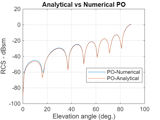
The RCS computation is done in the elevation plane at azimuth = 0 deg. The electric-field polarization vector is set to HH. This implies a horizontal component on transmit and horizontal component on receive is used for the RCS calculation. The results for the RCS from the toolbox are compared with the analytical results provided in [1].
az = 0;
el = 0.05:1:90;
sigma = rcs(p,f1,az,el,Polarization="HH");
asigma1 = rectPlateRCS(L,W,f1,az,90-el);
figure
plot(el,sigma,el,asigma1)
grid on
xlabel("Elevation angle (deg.)")
ylabel("RCS - dBsm")
title("Analytical vs Numerical PO")
legend("PO-Numerical","PO-Analytical",Location="best")

Circular Plate RCS Parameters Setup
Define the physical dimensions of the circular plate. The circular plate is described using an STL file. All dimensions are in meters.
R = 10.16e-2;
pc = platform;
pc.FileName = "circular_plate.stl";
pc.Units = "m";
Analyze and Compare with Analytical Result
As before compare the results from the RCS function in the toolbox with the analytical expression provided in [1]. The RCS calculation is done in the elevation plane between 0 and 90 deg.
az = 0;
el = 0.05:1:90;
sigmaV = rcs(pc,f1,az,el,Polarization="HH");
asigma1 = circPlateRCS(R,f1,90-el);
figure
plot(el,sigmaV,el,asigma1)
grid on
xlabel("Elevation angle (deg.)")
ylabel("RCS - dBsm")
title("Analytical vs Numerical PO")
legend("PO-Numerical","PO-Analytical",Location="best")

NASA Almond Setup
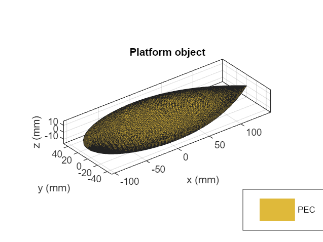
The third structure is the NASA almond shape described in [2]. This is a classic shape for benchmarking the performance of high-frequency electromagnetic solvers. The mathematical expressions in [2] have been used to create the STL file that describes the almond shape.
p = platform;
p.FileName = "NASA-Almond.stl";
p.Units = "m";
figure
show(p)

Analysis Parameters
Since the physical optics solver is only applicable at large ka values, we compare the results produced by the Antenna Toolbox with those published in [2]. The results produced by the toolbox will be from both solvers, the physical optics (PO) and the Method-of-Moments(MoM). The wavelength at 7 GHz is approximately 4.3 cm. We refine the mesh to be slightly finer than this using the criterion.
f2 = 7e9;
m = mesh(p,MaxEdgeLength=0.0035)
m =
  MeshReader with properties:

                Points: [3×4173 double]
             Triangles: [4×8342 double]
            Tetrahedra: []
         MaxEdgeLength: 0.0035
         MinEdgeLength: 0.0026
            GrowthRate: 0.5000
    MinimumMeshQuality: 0.0790
              MeshMode: 'manual'
az = 0:1:180;
el = 0;
RCS Calculation with HH-Polarization
Calculate the RCS for the HH-polarization condition in which the transmitted and received field is horizontally polarized.
sigmahh_po = rcs(p,f2,az,el,Solver="PO",...
    EnableGPU=false,Polarization="HH");

sigmahh_mom = rcs(p,f2,az,el,Solver="MoM",...
    Polarization="HH");
RCS Calculation with VV-Polarization
Calculate the RCS for the VV-polarization condition in which the transmitted and received field is vertically polarized.
sigmavv_po = rcs(p,f2,az,el,Solver="PO",...
    EnableGPU=false,Polarization="VV");

sigmavv_mom = rcs(p,f2,az,el,Solver="MoM",...
    Polarization="VV");
Plot Results
Overlay the plots from both solvers for both polarizations to compare. Notice that the full-wave MoM solver extracts all the phenomenon that contribute to the scattered field. In contrast the PO solver being a first-order approximation is able to predict the level of RCS but averages out the variations at the different angles. This is expected since the PO solver assumes that the surface current density outside the illuminated region, i.e. the shadow region is zero, thus not contributing to the scattered field.
figure
plot(az,sigmahh_mom,az,sigmahh_po,az,sigmavv_mom,az,sigmavv_po,LineWidth=2)
ax = gca;
ax.YLim = [-70,-15];
title("RCS Comparison, MoM vs. PO")
xlabel("Azimuth, deg.")
ylabel("Magnitude, dBsm")
grid on
legend("HH-pol, MoM","HH-pol, PO", "VV-pol, MoM","VV-pol, PO",Location="best")

Dielectric NASA Almond
The NASA Almond structure results plotted in the previous section was made out of a metal (Perfect Electric Conductor - PEC) and therefore an STL file based description was adequate. To consider the same structure made with a dielectric material as discussed in [3], you need additional information to be provided about the volumetric properties. To describe this use a MAT file based input to specify the structure. In this file specify the Points, Triangles and Tetrahedra fields to completely specify the surface and volume geometry and in addition provide the relative permittivity and loss tangent for material properties.
p = platform;
p.FileName = "NASA_Diel_Almond_24KTri_400KTets.mat"; %f = 2.58e9
p.Units = "m"
p =
  platform with properties:

         FileName: "NASA_Diel_Almond_24KTri_400KTets.mat"
            Units: "m"
    UseFileAsMesh: 0
             Tilt: 0
         TiltAxis: [1 0 0]
p.UseFileAsMesh = 1;
figure
show(p)

This is a structure with close to half a million elements in the mesh. To solve, use the FMM accelerated solver. Since the calculation takes several minutes per angle, the results from the solver are shown in the figure below overlaid with results from [3] for comparison. The frequency of analysis is 2.58 GHz.
RCS Calculation for HH-polarization
Uncomment the lines of code in this section to calculate the RCS for the HH-polarization condition in which the transmitted and received field is horizontally polarized.
f3 = 2.58e9;
sigma_almondHH = -inf*ones(1,numel(az));
h1 = figure;
plot(az,sigma_almondHH,LineWidth=2)
xlabel("Azimuth angle (deg.)")
ylabel("RCS (dBsm)")
title("HH-pol RCS at el =0 deg.")
grid on
for i = 1:numel(az)
    sigma_almondHH(i) = rcs(p,f3,az(i),0,Solver="FMM",Polarization="HH");
    figure(h1)
    plot(az,sigma_almondHH,LineWidth=2)
end

RCS Calculation for VV-Polarization
Uncomment the lines of code in this section to calculate the RCS for the VV-polarization condition in which the transmitted and received field is vertically polarized. For this polarization case, the azimuth sweep has been non-uniformly discretized so as to take larger steps for most of the sweep range and closer to the sharp null, as seen in [3], the step size is reduced.
az = [0:2:130,130.5:0.5:150,152:2:180];
sigma_almondVV = -inf*ones(1,numel(az));
h2 = figure;
plot(az,sigma_almondVV,LineWidth=2)
xlabel("Azimuth angle (deg.)")
ylabel("RCS (dBsm)")
title("VV-pol RCS at el =0 deg.")
grid on
tstart = tic
for i = 1:numel(az)
    sigma_almondVV(i) = rcs(p,f3,az(i),0,Solver="FMM",Polarization="VV");
    figure(h2)
    plot(az,sigma_almondVV,LineWidth=2)
end

Summary
The RCS benchmarking results compare favorably with published results using analytical techniques as well as other numerical solvers.
References
[1] Mahafza, Bassem R. Radar Systems Analysis and Design Using Matlab. Boca Raton: Chapman & Hall/CRC, 2000.
[2] Woo, A.C., H.T.G. Wang, M.J. Schuh, and M.L. Sanders. “EM Programmer’s Notebook-Benchmark Radar Targets for the Validation of Computational Electromagnetics Programs.” IEEE Antennas and Propagation Magazine 35, no. 1 (February 1993): 84–89. https://doi.org/10.1109/74.210840.