Double-Slot Cavity Patch on TMM10 Substrate
This example shows you how to create a custom slot cavity patch using custom antenna geometry and thick dielectric substrate. A double slot cavity patch consists of a double slot patch, backed by a cavity and probe-fed. The cavity is filled with TMM10 substrate. The cavity backing helps to reduce back radiation. You can use this antenna for microwave imaging by placing the antenna close to the human body.
Below is the picture of the fabricated slotted patch antenna.

Fabricated slotted patch antenna (with permission from Antenna Lab, WPI)
Create a Double Slot Patch
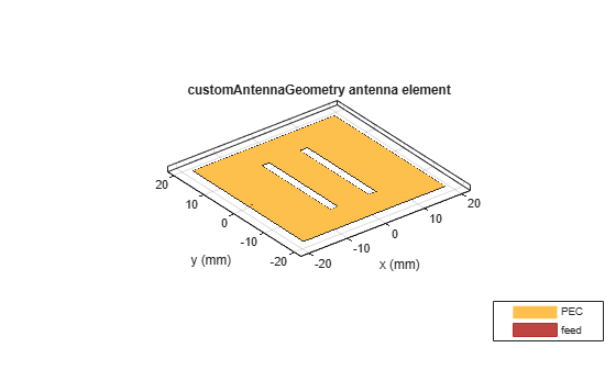
A double slot patch is not available as part of the Antenna Toolbox™ Library. However, you can create the geometry using basic rectangle shape primitive. You can put this information into a customAntennaGeometry object and perform Boolean operations to create the slots.
rect1 = antenna.Rectangle(Length=37e-3, Width=37e-3);
p1 = getShapeVertices(rect1);
slot1 = antenna.Rectangle(Length=2e-3, Width=23e-3,               ...
     Center=[-5e-3, 0], NumPoints=[5 10 5 10]);
p2 = getShapeVertices(slot1);
slot2 = antenna.Rectangle(Length=2e-3, Width=23e-3,               ...
     Center=[ 5e-3, 0], NumPoints=[5 10 5 10]);
p3 = getShapeVertices(slot2);
feed1 = antenna.Rectangle(Length=0.5e-3, Width=0.5e-3,            ...
     Center=[-17.25e-3 0]);
p4 = getShapeVertices(feed1);

ant = customAntennaGeometry;
ant.Boundary = {p1,p2,p3,p4};
ant.Operation = 'P1-P2-P3+P4';
ant.FeedLocation = [-17.5e-3,0,0];
ant.FeedWidth = 0.5e-3;
figure
show(ant)
Provide Cavity Backing with Probe Feed
Use the slot patch created as an exciter for the cavity and enable probe feed. Below you see the patch antenna structure on an air substrate.
c = cavity(Exciter=ant, Length=57e-3, Width=57e-3, Height= ...
    6.35e-3, Spacing=6.35e-3, EnableProbeFeed=1);
figure
show(c)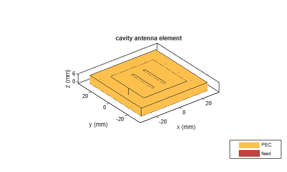
Calculate the Antenna Impedance
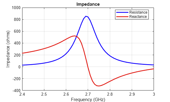
Calculate the antenna impedance over the range of 2.4 GHz to 3 GHz. From the figure, observe that the antenna resonates around 2.76 GHz.
figure
impedance(c, linspace(2.4e9, 3.0e9, 61));
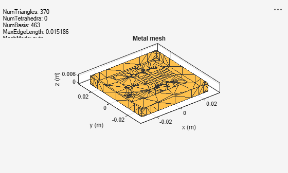
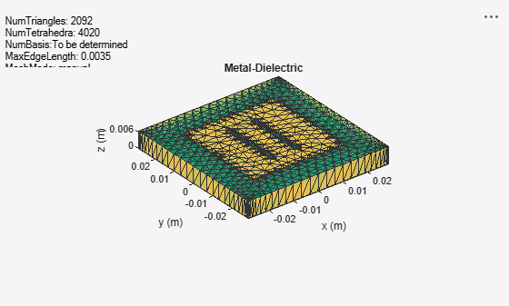
Visualize the Antenna Mesh
At the highest frequency of 2.2 GHz, the wavelength (lambda) in TMM10 dielectric is 43.6 mm. So the substrate thickness is lambda/7. So to make the thick substrate accurate thick substrate, two layers of tetrahedra are automatically generated.
figure
mesh(c);
Add a Dielectric Substrate
Fill the space between the cavity and the patch with Rogers TMM10 substrate from the dielectric catalog.
c.Substrate = dielectric("TMM10");
show(c)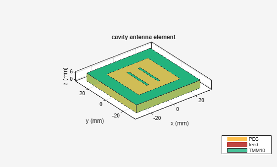
Meshing the Antenna
Mesh the antenna with a maximum edgelength of 3.5 mm.
mesh(c,MaxEdgelength=3.5e-3);
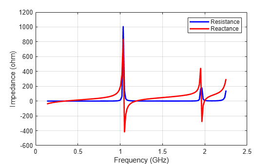
Calculate the Antenna Impedance
The effect of the dielectric constant is to move the resonance by a factor of sqrt(9.8) ~ 3, approximately. So antenna miniaturization is achieved by adding a dielectric substrate. However, as the dielectric constant of the substrate increases the antenna higher Q-factor creates a sharp resonance. Due to the large numbers of frequency steps involved, the results are pre-computed and stored. Only one of the highest frequency computations is shown.
zl = impedance(c, 2.2e9);
load cavitypatch;
figure
plot(freq./1e9, real(Z), 'b', freq./1e9, imag(Z), 'r', LineWidth=2);
xlabel('Frequency (GHz)');
ylabel('Impedance (ohm)');
legend('Resistance','Reactance');
grid on;
Fabricated Slot-patch Antenna
The double slot patch antenna was manufactured and its reflection coefficient was measured at the Antenna Lab in Worcester Polytechnic Institute (WPI). As seen from the plot below, a very good agreement is achieved at the lower frequency. At the upper frequency the difference in the reflection coefficient is around 3.5%. This could be due to the SMA connector present on the actual antenna or the frequency variation in the dielectric constant for the substrate.
figure
plot(freq./1e9,s11_meas,'-r', LineWidth=2);
grid on;
hold on
plot(freq./1e9,s11_sim,'-b', LineWidth=2);
grid on;
xlabel('Freq (GHz)')
ylabel('S11 (dB)')
axis([0.5,2.2,-5,0])
title('Antenna S11 Data')
legend('Measured','Simulated', Location="best")
