Deploy Flexible Solar Panel Array on CubeSat
This example shows how to compute the flexible motion of a CubeSat solar panel arrays during deployment, and their effect on CubeSat attitude and camera performance.
CubeSats are used extensively for Earth observation and scientific missions, where high-precision pointing and stable imaging are critical. Many CubeSats use deployable solar panel arrays to maximize power generation within the constraints of a compact launch volume. However, the deployment and subsequent flexible motion of these panels can introduce dynamic disturbances to the satellite bus. These disturbances, if not properly understood and mitigated, can degrade the performance of sensitive payloads such as cameras and imagers, leading to blurred images or loss of pointing accuracy.
Explore Model
Open the model.
open_system("CubeSatSSMB_OrbitSL");In this model:
Simscape™ Multibody™ is used to calculate the flexible motion of the solar panel arrays as they are deployed.
Aerospace Blockset™ is used to calculate the CubeSat's orbit and attitude dynamics.
DSP System Toolbox™ is used to calculate camera performance.
The Aerospace Blockset™ interface to Unreal Engine® (UE) enables visualization.
The attitude dynamics of the CubeSat are coupled with the flexible motion of the solar panel arrays, allowing for direct simulation of the combined system.
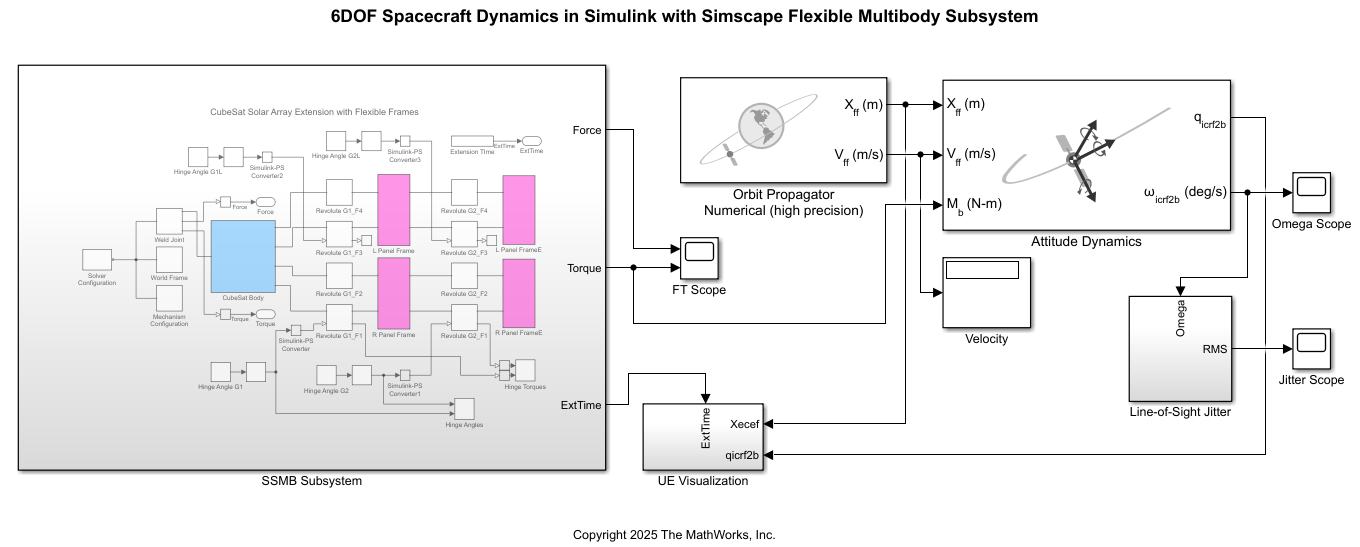
Simscape Multibody
The SSMB subsystem uses reduced-order models (ROMs) of the solar panel array structures for its calculations in order to accurately capture the essential dynamic behavior while minimizing computational cost. Therefore, the first step in creating this model is to calculate the ROMs for each panel in the solar arrays.
The CubeSat has two panels on each side, an inner one with two hinges on each side, and an outer one with two hinges on only one side. The Flexible Body Model Builder (Simscape Multibody) app is used to calculate each of these ROMs.
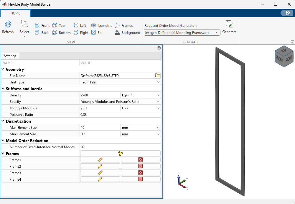
The figure shows the inner panel in the app. Material properties are set, as well as the automatic mesh elements sizes and the number of fixed-interface normal modes. Frames define the connection of the structure with adjacent structures. In this case, a frame is defined at the center of each hinge mounting surface.
To generate the ROMs, select a ROM generator and then click Generate. This example uses ROMs created with the Integro-Differential Modeling Framework, which is available as an add-on.
In the SSMB subsystem, each solar panel is represented by a Reduced Order Flexible Solid (Simscape Multibody) block, which reads in the corresponding ROMs. The main body of the CubeSat, or bus, is modeled as a rigid structure to which the inner solar panels are attached.
The hinge angles are changed at a uniform rate over the first ten seconds of simulation. The solar panel array begins in its closed, or stowed, state, and opens completely by the end of ten seconds. The simulation continues for an additional five seconds to allow the flexible motions to diminish.
Gravity is set to zero for the SSMB subsystem. The torques that the hinges apply on the bus are output from the subsystem for use in the orbital dynamics calculations and are the only connection between the Simscape and Simulink® portions of the model.
The angular velocity of the CubeSat bus, calculated by the Attitude Dynamics block, can potentially impact the flexible motions calculated by the Simscape Multibody subsystem. For simplicity, however, this feedback is not included in this model.
CubeSat Dynamics
All orbital dynamics are calculated using the Aerospace Blockset. An equatorial orbit is defined in the Orbit Propagator Numerical (high precision) block, which outputs the CubeSat position and velocity in an Earth-centered Earth-fixed (ECEF) coordinate system. These values, as well as the hinge torques from Simscape, are input into the Attitude Dynamics block. This block outputs a quaternion and rotation rate in inertial (International Celestial Reference Frame or Earth-centered inertial) coordinates.
To change the orbit start date and time, modify the Julian start values in both the Orbit Propagator Numerical (high precision) and Attitude Dynamics blocks. Then, within the UE Visualization subsystem, enter the same values in the Simulation 3D Space Environment and DCM ECI to ECEF blocks.
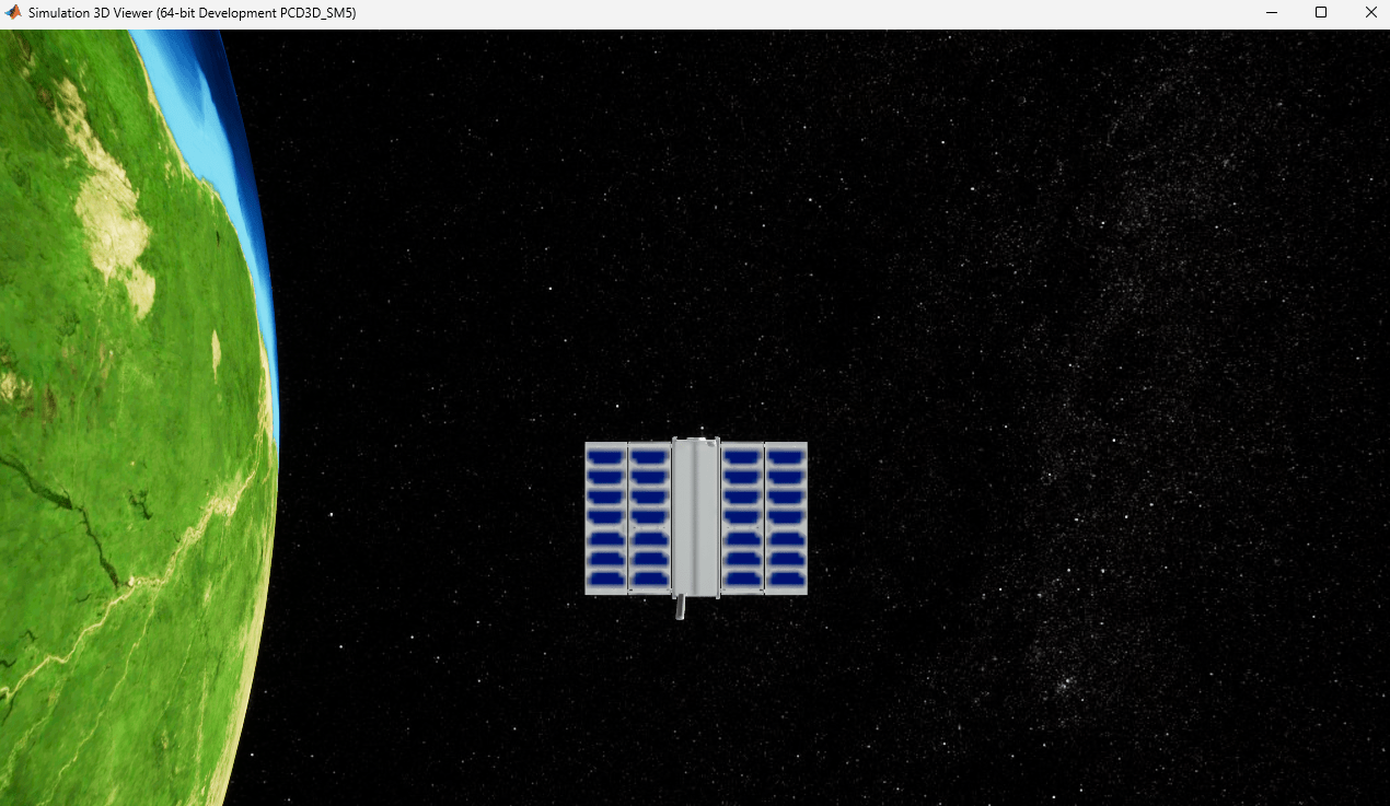
Visualization
Visualization of the CubeSat in orbit is provided by Unreal Engine using the Earth scene, after applying the appropriate transformations.
Camera Performance
The effect of solar panel array vibrations on the CubeSat's attitude is quantified by calculating the line-of-sight (LOS) jitter of a camera mounted on the bus. The angular rate output, omega, from the Attitude Dynamics block is used to compute the RMS LOS jitter, providing a direct measure of potential image degradation due to flexible body motion.
The RMS block from the DSP System Toolbox™ is used for this calculation. Slow drifting motion is removed from the angular rate signal with an analog high-pass filter.
Simulate Model
Click Run to start the simulation. Small solver tolerances help to achieve simulation accuracy. A relative tolerance of 1E-8 and an absolute tolerance of 1E-9 are used to maintain good resolution of vibrations in the solar panel arrays.
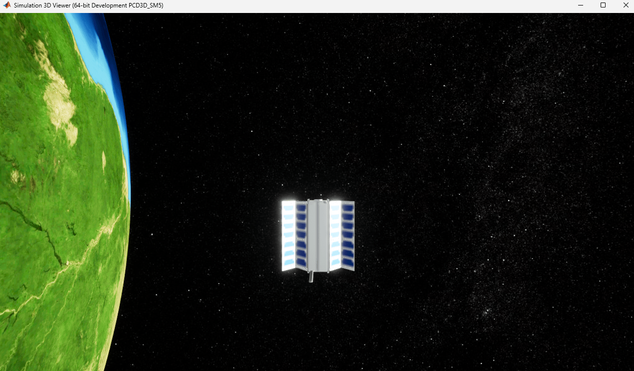
The Sample time parameter in the Simulation 3D Scene Configuration block sets the UE visualization update frequency to every 0.01 seconds. To visualize the simulation, click the Simulation 3D Viewer window and press the number 6 key. For more information on navigation in this 3D environment, see Navigate in Unreal Engine Environment (Simulink 3D Animation).
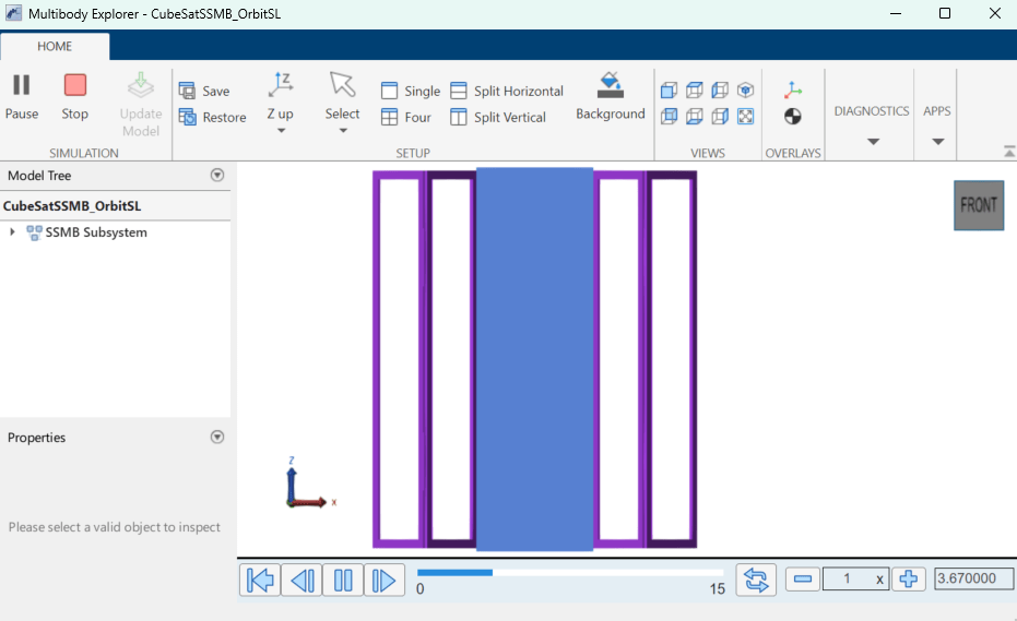
The Multibody Explorer tool and a variety of scopes show the progression of the simulation.
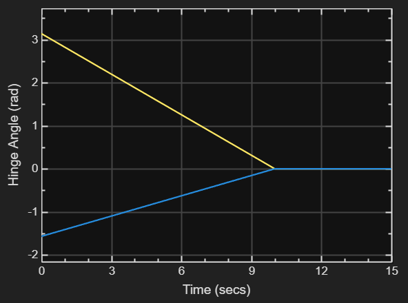
The solar panel array hinge angles in radians are shown in blue for the hinges mounted on the bus and yellow for the hinges mounted between the inner and outer panels.
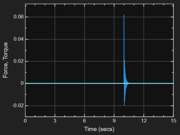
The forces and torques on the hinges mounted on the bus are summed and output from the Simscape Multibody subsystem.
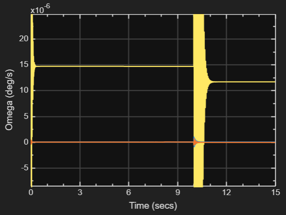
Angular rates are output from the Attitude Dynamics block and used for the LOS jitter calculation. The motion caused by the abrupt stop in hinge angle at ten seconds is significantly greater than the corresponding abrupt start at zero seconds, due to the solar panel arrays being fully extended.
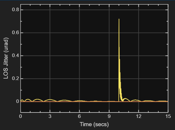
The LOS jitter scope shows the RMS of the angular displacement of the CubeSat bus in units of microradians, with drift filtered out. All three channels of omega are calculated, but only roll is significant due to the satellite's configuration. For more information, see CubeSat.
See Also
Topics
- Reduced Order Flexible Solid (Simscape Multibody)