NR Uplink Channel State Information Estimation Using SRS
R2026bThis example shows how to use sounding reference signals (SRS) for synchronization, channel estimation, and uplink channel state information (CSI) estimation.
Introduction
Sounding reference signals are uplink physical signals used by user equipment (UE) for uplink channel sounding and synchronization. The gNB determines transmission parameters for codebook-based PUSCH: the number of transmission layers, transmit precoding matrix indicator (TPMI), and modulation and coding scheme (MCS) index. The gNB signals these to the UE via DCI using two fields as specified in TS 38.212 Table 7.3.1.1. These fields are "Modulation and coding scheme" and "Precoding information and number of layers".
3GPP 5G NR specifications do not define an uplink CSI reporting framework analogous to the downlink one. In 5G Toolbox, the nrCSIReportSRS function derives uplink transmission parameters from SRS measurements and returns recommended values for rank, MCS, and TPMI.
This example demonstrates how to use SRS to select the appropriate TPMI under frequency-selective time-varying noisy channels for an assumed rank. Uplink codebook-based transmissions use TPMIs, as defined in TS 38.211 Section 6.3.1.5 [ 1 ].
This example performs a simulation including:
SRS configuration and transmission
Perfect and practical synchronization and channel estimation
Signal-to-noise ratio (SNR) estimation
PMI selection
PMI selection performance assessment
Simulation Length and SNR
Set the length of the simulation in terms of the number of 10 ms frames. Set the SNR points to simulate. The SNR is defined per RE and applies to each receive antenna.
numFrames = 1; % 10 ms frames
snr = 20; % SNR in dB
Carrier and SRS Configuration
Set the key parameters of the simulation. These include:
The bandwidth in resource blocks (12 subcarriers per resource block)
Subcarrier spacing: 15, 30, 60, 120, 240, 480, 960 (kHz)
Cyclic prefix length: normal or extended
Number of transmit and receive antennas: 1, 2, 4 or 8.
Number of layers. It must be lower than or equal to the number of transmit and receive antennas.
The SRS parameters specified include:
Number of SRS antenna ports: 1,2,4,8
Number of OFDM symbols allocated for SRS per slot: 1,2,4,8,10,12,14
Starting OFDM symbol of the SRS transmission within a slot. It must be (0 to 13) for normal CP and (0 to 11) for extended CP.
Starting position of the SRS in frequency specified in RBs
Bandwidth and frequency hopping configuration
CSRS,BSRS, andBHop. SetBHop >= BSRSto disable frequency hopping.Transmission comb to specify the SRS frequency density in subcarriers: 2,4,8
Number of repeated SRS symbols within a slot. It disables frequency hopping in blocks of
Repetitionsymbols. SetRepetition = 1for no repetition.Periodicity and offset of the SRS in slots.
Resource type can be 'periodic', 'semi-persistent', and 'aperiodic'. The frequency hopping pattern is reset for aperiodic SRS resource types in every slot.
% Create carrier configuration
carrier = nrCarrierConfig;
carrier.NSizeGrid = 52;          % Bandwidth in number of resource blocks (52RBs at 15kHz SCS for 10MHz BW)
carrier.SubcarrierSpacing = 15;  % 15, 30, 60, 120, 240, 480, 960 (kHz)
carrier.CyclicPrefix = 'Normal'; % 'Normal' or 'Extended'

nTxAnts = 2;  % Number of transmit antennas (1,2,4,8)
nRxAnts = 2;  % Number of receive antennas
nLayers = min(nTxAnts,nRxAnts);

% Configure a periodic multi-port SRS and enable frequency hopping
srs = nrSRSConfig;
srs.NumSRSSymbols = 4;          % Number of OFDM symbols allocated per slot (1,2,4,8,10,12,14)
srs.SymbolStart = 0;            % Starting OFDM symbol within a slot
srs.NumSRSPorts = nTxAnts;      % Number of SRS antenna ports (1,2,4,8).
srs.FrequencyStart = 0;         % Frequency position of the SRS in BWP in RBs
srs.NRRC = 0;                   % Additional offset from FreqStart specified in blocks of 4 PRBs (0...67)
srs.CSRS = 14;                  % Bandwidth configuration C_SRS (0...63). It controls the allocated bandwidth to the SRS
srs.BSRS = 0;                   % Bandwidth configuration B_SRS (0...3). It controls the allocated bandwidth to the SRS
srs.BHop = 0;                   % Frequency hopping configuration (0...3). Set BHop < BSRS to enable frequency hopping
srs.KTC = 2;                    % Comb number (2,4,8). Frequency density in subcarriers
srs.Repetition = 2;             % Repetition (1,2,4,5,6,7,8,10,12,14). It disables frequency hopping in blocks of |Repetition| symbols
srs.SRSPeriod = [2 0];          % Periodicity and offset in slots. SRSPeriod(2) must be < SRSPeriod(1)
srs.ResourceType = 'periodic';  % Resource type ('periodic', 'semi-persistent','aperiodic'). Use 'aperiodic' to disable inter-slot frequency hopping

% Configure PUSCH for codebook-based uplink transmission. The PUSCH
% configuration is used by nrCSIReportSRS for PMI selection and for MCS
% calculations, update the PUSCH PRBSet as number of resource blocks of SRS
pusch = nrPUSCHConfig;
pusch.TransmissionScheme = "codebook";    % PUSCH transmission scheme, specified as 'nonCodebook' or 'codebook'
pusch.NumAntennaPorts = srs.NumSRSPorts;  % Number of PUSCH antenna ports (1,2,3,4,8)
pusch.PRBSet = 0:srs.NRB-1;               % PRB allocation of the PUSCH within the BWP

% Configure PUSCH symbol allocation as [0 12] if extended cyclic prefix is
% used
if strcmpi(carrier.CyclicPrefix,'extended')
    pusch.SymbolAllocation = [0 12];
end
Synchronization, Channel Estimation and CSI Measurement Configuration
This example performs synchronization and channel estimation in SRS candidate slots. Timing and channel estimates are updated only in slots containing SRS transmissions. In frequency-hopping SRS setups, channel estimates are only updated in those resource blocks containing SRS symbols. When there is no SRS transmission, CSI acquisition from previous slots are used. Similarly, noise power estimates are updated only in SRS candidate slots.
The logical variable practicalSynchronization controls channel synchronization behavior. When set to true, the example performs practical synchronization based on the values of the received SRS. When set to false, the example performs perfect synchronization. Synchronization is performed only in slots where the SRS is transmitted to keep perfect and practical channel estimates synchronized.
practicalSynchronization = true;
This example estimates CSI by splitting the carrier bandwidth into a number of subbands. Specify the size of the frequency subbands in RB
csiSubbandSize = 4; % Number of RBs per subband
Propagation Channel Model Configuration
Create a TDL channel model object and specify its propagation characteristics. Select the channel delay spread and maximum Doppler shift to create a time-varying and frequency-selective channel within the simulation duration and carrier bandwidth.
channel = nrTDLChannel;
channel.DelayProfile = 'TDL-C';
channel.DelaySpread = 40e-9;
channel.MaximumDopplerShift = 30;
channel.NumTransmitAntennas = nTxAnts;
channel.NumReceiveAntennas = nRxAnts;
channel.Seed = 5;

% Set channel sample rate
ofdmInfo = nrOFDMInfo(carrier);
channel.SampleRate = ofdmInfo.SampleRate;

% Get the maximum delay of the channel
chInfo = info(channel);
maxChDelay = chInfo.MaximumChannelDelay;

% Reset random generator for reproducibility
rng('default');
Processing Loop
Measure the CSI per slot. The CSI is obtained using the following steps:
Generate resource grid. Use SRS symbols and indices to create a resource element (RE) grid.
Generate waveform. The generated grid is then OFDM modulated.
Model noisy channel. The waveform is passed through a TDL fading channel. AWGN is added. The SNR for each layer is defined per RE and per receive antenna.
Perform synchronization and OFDM demodulation. For perfect synchronization, the channel impulse response is reconstructed and used to synchronize the received waveform. For practical synchronization, the received waveform is correlated with the SRS. The synchronized signal is then OFDM demodulated.
Perform channel estimation. For perfect channel estimation, the channel impulse response is reconstructed and OFDM demodulated to provide a channel estimate. For practical channel estimation, the transmitted SRS is used.
PMI selection. The SRS-based channel estimate is used to select the best PMI in each CSI estimation subband. The PMI selection criterion maximizes the sum rate.
PMI selection SINR loss. The SINR loss is calculated by comparing the post-equalization SINR with the estimated and ideal PMIs. Ideal PMIs are selected using perfect channel estimates.
% Number of slots to simulate
numSlots = numFrames*carrier.SlotsPerFrame;

% Total number of subcarriers and symbols per slot
K = carrier.NSizeGrid * 12;
L = carrier.SymbolsPerSlot;

% Initialize arrays storing channel estimates
allTxGrid = zeros([K L*numSlots nTxAnts]);

slotGridSize = [K L nRxAnts nTxAnts];
hEst = zeros(slotGridSize);
hestInterp = zeros(slotGridSize);
hEstUpdate = zeros(slotGridSize);

totalGridSize = [K L*numSlots nRxAnts nTxAnts];
allHest = zeros(totalGridSize);
allHestPerfect = zeros(totalGridSize);
allHestInterp = zeros(totalGridSize);

% Initialize noise power estimate
nvar = 0;

% Calculate the number of CSI subbands for the carrier
numCSISubbands = ceil(carrier.NSizeGrid/csiSubbandSize);

% Initialize SINR per subband, slot, and PMI
sinrSubband = zeros([numCSISubbands numSlots]);

% Initialize PMI matrix and SINR loss
pmi = NaN(numCSISubbands,numSlots);
pmiPerfect = pmi;
loss = zeros(numCSISubbands,numSlots);
% Initialize timing estimation offset
offset = chInfo.ChannelFilterDelay;

% Calculate SRS CDM lengths
cdmLengths = hSRSCDMLengths(srs);

% OFDM symbols used for CSI acquisition
csiSelectSymbols = srs.SymbolStart + (1:srs.NumSRSSymbols);

for nSlot = 0:numSlots-1

    % Update slot counter
    carrier.NSlot = nSlot;

    % Generate SRS and map to slot grid
    [srsIndices,srsIndInfo] = nrSRSIndices(carrier,srs);
    srsSymbols = nrSRS(carrier,srs);

    % Create a slot-wise resource grid empty grid and map SRS symbols
    txGrid = nrResourceGrid(carrier,nTxAnts);
    txGrid(srsIndices) = srsSymbols;

    % Determine if the slot contains SRS
    isSRSSlot= ~isempty(srsSymbols);

    % OFDM Modulation
    [txWaveform,waveformInfo] = nrOFDMModulate(carrier,txGrid);

    txWaveform = [txWaveform; zeros(maxChDelay, size(txWaveform,2))]; %#ok<AGROW> % required later to flush the channel filter to obtain the received signal

    % Transmission through channel
    [rxWaveform,pathGains] = channel(txWaveform);

    % Add AWGN to the received time domain waveform
    % Normalize noise power to take account of sampling rate, which is
    % a function of the IFFT size used in OFDM modulation. The SNR
    % is defined per RE for each receive antenna (TS 38.101-4).
    SNR = 10^(snr/10);
    N0 = 1/sqrt(nRxAnts*waveformInfo.Nfft*SNR);
    nvarPerfect = N0^2*waveformInfo.Nfft; % perfect noise variance
    noise = N0*randn(size(rxWaveform),like=1i);

    rxWaveform = rxWaveform + noise;

    % Perform timing offset estimation
    pathFilters = getPathFilters(channel);

    % Timing estimation is only performed in the slots where the SRS is
    % transmitted to keep the perfect and practical channel estimation
    % synchronized.
    if isSRSSlot
        if practicalSynchronization
            % Practical synchronization. Correlate the received waveform
            % with the SRS to give timing offset estimate
            offset = nrTimingEstimate(carrier,rxWaveform,srsIndices,srsSymbols);
        else
            offset = nrPerfectTimingEstimate(pathGains,pathFilters); %#ok<UNRCH>
        end
    end

    % Perform OFDM demodulation
    rxGrid = nrOFDMDemodulate(carrier,rxWaveform(1+offset:end,:));
    hEstPerfect = nrPerfectChannelEstimate(carrier,pathGains,pathFilters,offset);

    % Perform practical channel estimation
    % Update channel estimates only in the symbols and RBs containing SRS
    % in this slot and hold the estimates from the previous slot in other
    % locations. nvar is not updated when there is no SRS transmission. Use
    % a time-averaging window that covers all the SRS symbols transmitted.
    if isSRSSlot % this slot contains an SRS transmission
        [hEst,nvar] = nrChannelEstimate(carrier,rxGrid,srsIndices,srsSymbols,'AveragingWindow',[0 7],'CDMLengths',cdmLengths);

        % Use channel estimate from previous slot for OFDM symbols before the first SRS symbol
        hestInterp = repmat(hestInterp(:,end,:,:),1,carrier.SymbolsPerSlot);

        % Update channel estimate in OFDM symbols and RB where the SRS is
        % present and hold all channel estimates until the end of the slot
        firstSymbol = srs.SymbolStart+1;
        lastSymbol = srs.SymbolStart + srs.NumSRSSymbols;
        hEstUpdate(:,firstSymbol:lastSymbol,:,:) = hEst(:,firstSymbol:lastSymbol,:,:);
        hEstUpdate(:,lastSymbol:L,:,:) = repmat(hEst(:,lastSymbol,:,:),1,carrier.SymbolsPerSlot-lastSymbol+1);

        idxHEstUpdate = hEstUpdate ~= 0; % Indices of updated channel estimates
        hestInterp(idxHEstUpdate) = hEstUpdate(idxHEstUpdate);

        % PMI Selection using practical channel estimation
        % Select the precoder matrix indicators for a number of layers using
        % the interpolated channel estimates in the OFDM symbols specified by
        % csiSelectSymbols. The PMIs are estimated per CSI subband
        [csiPractical,csiinfoPractical] = nrCSIReportSRS(carrier,srs,pusch,hestInterp,nvar,"TPMIFormatIndicator","subband","SubbandSize",csiSubbandSize,"RankRestriction",[zeros(1,nLayers-1) 1 zeros(1,8-nLayers)]);

        % PMI Selection using perfect channel estimation
        [csiPerfect,csiinfoPerfect] = nrCSIReportSRS(carrier,srs,pusch,hEstPerfect,nvarPerfect,"TPMIFormatIndicator","subband","SubbandSize",csiSubbandSize,"RankRestriction",[zeros(1,nLayers-1) 1 zeros(1,8-nLayers)]);

        % PMI selection SINR loss
        % Calculate the performance loss as a ratio of the
        % post-equalization SINRs with PMIs selected using a practical
        % channel estimate and PMIs selected using a perfect channel
        % estimate in SRS symbols.
        sinrLoss = hPMISelectionSINRLoss(carrier,srs,csiinfoPractical.PrecodingMatrix,csiinfoPerfect.PrecodingMatrix,hEstPerfect(:,csiSelectSymbols,:,:),nvarPerfect,csiSubbandSize);
    else % Hold previous channel estimates if this slot does not contain SRS
        hestInterp = repmat(hestInterp(:,end,:,:),1,carrier.SymbolsPerSlot);
    end

    % Assign the PMI calculated from CSI report. Use the PMI calculated
    % from the previous slot, if the current slot do not contain SRS
    pmi(:,nSlot+1) = csiPractical.TPMI;
    sinrSubband(:,nSlot+1) = sum(csiinfoPractical.SINRPerSubband,2); % Sum across all the layers

    loss(:,nSlot+1) = sinrLoss;
    pmiPerfect(:,nSlot+1) = csiPerfect.TPMI;

    % Save a copy of all transmitted OFDM grids and channel estimates for
    % display purposes
    thisSlot = nSlot*L + (1:L); % Symbols of the current slot
    allTxGrid(:,thisSlot,:) = txGrid;
    allHest(:,thisSlot,:,:) = hEst;
    allHestInterp(:,thisSlot,:,:) = hestInterp;
    allHestPerfect(:,thisSlot,:,:) = hEstPerfect;

end
Results
This section displays these results for all configured frames:
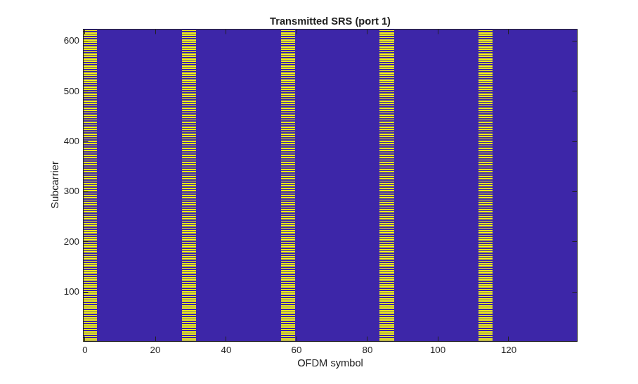
Transmitted OFDM grid containing SRS
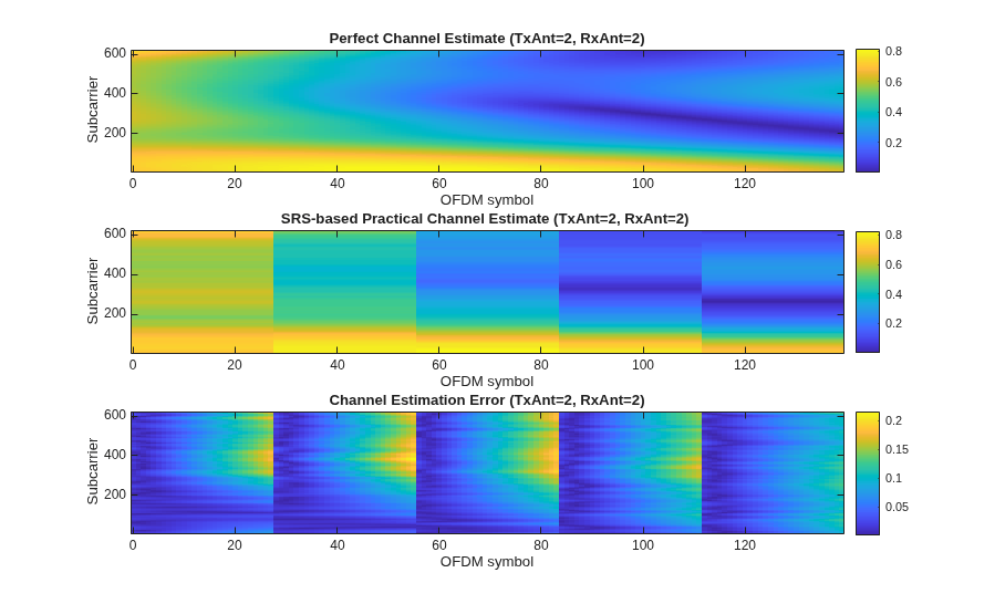
Perfect and practical channel estimates, and channel estimation error. The error is calculated as the absolute value of the difference between the perfect and practical channel estimates.
Selected PMI using perfect and practical channel estimates, and the PMI absolute error.
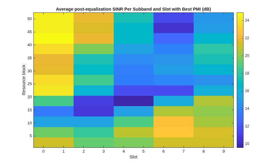
Average post-equalization SINR per subband with best estimated PMI
SINR performance loss
% Create x-axis and y-axis vectors
symbols = 0:(carrier.NSlot+1)*carrier.SymbolsPerSlot-1;
slots = 0:carrier.NSlot;
subcarriers = 1:carrier.NSizeGrid*12;
resourceBlocks = 1:carrier.NSizeGrid;
Display the transmitted OFDM grid containing SRS
figure
imagesc(symbols,subcarriers,abs(allTxGrid(:,:,1,1)));
xlabel('OFDM symbol'); ylabel('Subcarrier'); axis xy;
title('Transmitted SRS (port 1)');
Display perfect and practical channel estimates, and channel estimation error per OFDM symbol and subcarrier. The channel estimation error is defined as the absolute value of the difference between the perfect and practical channel estimates.
% Remove first OFDM symbols not containing SRS to improve visualization of
% channel estimation error
hEstInterp = allHestInterp;
idx = 1:(srs.SRSPeriod(2)*carrier.SymbolsPerSlot + srs.SymbolStart);
hEstInterp(:,idx,:,:) = NaN;
hEstInterp((srs.NRB*12+1):end,:,:,:) = NaN;

hChannelEstimationPlot(symbols,subcarriers,allHestPerfect,hEstInterp);
Display the selected PMI using perfect and practical channel estimates, and the PMI selection SINR loss per slot and RB. The SINR loss is defined as a ratio of the post-equalization SINR with estimated and perfect PMIs. Estimated PMIs are obtained using a practical channel estimate and perfect PMIs are selected using a perfect channel estimate.
% First expand loss from subbands into RBs for display purposes
pmiRB = hExpandSubbandToRB(pmi, csiSubbandSize, carrier.NSizeGrid);
pmiPerfectRB = hExpandSubbandToRB(pmiPerfect, csiSubbandSize, carrier.NSizeGrid);
lossRB = hExpandSubbandToRB(loss, csiSubbandSize, carrier.NSizeGrid);

hPMIPlot(slots,resourceBlocks,pmiRB,pmiPerfectRB,lossRB);
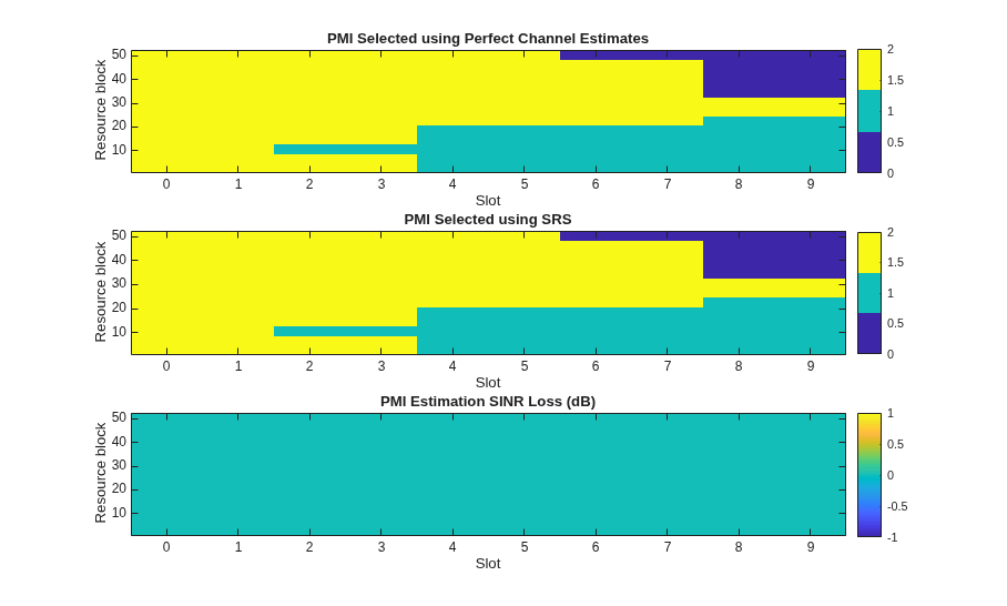
Next, compare the PMIs obtained using both perfect and practical channel estimates. This indicates the ratio of correct to total PMIs and the location in the resource grid where errors have occurred.
numLayers = min(size(allHestInterp,[3 4]));
if numLayers ~= 1
    pmiErr = sum( abs(pmi - pmiPerfect) > 0, [1 2])./ sum( ~isnan(pmi), [1 2]);

    TotPMIEst = sum(~isnan(pmi),[1 2]);
    fprintf('Number of estimated PMI: %d \n', TotPMIEst);
    fprintf('    Number of wrong PMI: %d \n', ceil(pmiErr*TotPMIEst));
    fprintf('         Relative error: %.1f (%%) \n', pmiErr*100);
else
    fprintf('For a single layer, PMI is always 0.\n');
end
Number of estimated PMI: 130
    Number of wrong PMI: 0
         Relative error: 0.0 (%)
Display the post-equalization SINR per slot and RB obtained with the PMI that maximizes the SINR per subband.
hBestSINRPlot(slots,resourceBlocks,sinrSubband,csiSubbandSize);
Summary and Further Exploration
This example shows how to use SRS for synchronization, channel estimation and PMI selection commonly employed in codebook-based uplink transmission modes. The example also evaluates the channel estimation and PMI selection performance loss using the post-equalization SINR.
You can investigate the performance of the channel estimation and PMI selection in more complex settings. Increase the SRS periodicity and observe how the channel estimates aging introduces a delay and worsens the post-equalization SINR. In addition, you can investigate the performance under frequency hopping conditions by setting the SRS parameters BHop < BSRS. In this setup, channel estimates aging is not uniform in frequency.
Appendix
This example uses the following helper functions:
References
3GPP TS 38.211. "NR; Physical channels and modulation" 3rd Generation Partnership Project; Technical Specification Group Radio Access Network.
3GPP TS 38.101-4. "NR; User Equipment (UE) radio transmission and reception. Part 4: Performance requirements" 3rd Generation Partnership Project; Technical Specification Group Radio Access Network.
Local functions
% Displays perfect and practical channel estimates and the channel
% estimation error for the first transmit and receive ports. The channel
% estimation error is defined as the absolute value of the difference
% between the perfect and practical channel estimates.
function hChannelEstimationPlot(symbols,subcarriers,allHestPerfect,allHestInterp)

    figure
    subplot(311)
    imagesc(symbols, subcarriers, abs(allHestPerfect(:,:,1,1)));
    axis xy; xlabel('OFDM symbol'); ylabel('Subcarrier');
    colorbar;
    title('Perfect Channel Estimate (TxAnt=2, RxAnt=2)');

    subplot(312)
    imagesc(symbols, subcarriers, abs(allHestInterp(:,:,1,1)), ...
            'AlphaData',~isnan(allHestInterp(:,:,1,1)))
    axis xy; xlabel('OFDM symbol'); ylabel('Subcarrier');
    colorbar;
    title('SRS-based Practical Channel Estimate (TxAnt=2, RxAnt=2) ');

    % Display channel estimation error, defined as the difference between the
    % SRS-based and perfect channel estimates
    subplot(313)
    hestErr = abs(allHestInterp - allHestPerfect);
    imagesc(symbols, subcarriers, hestErr(:,:,1,1),...
            'AlphaData',~isnan(hestErr(:,:,1,1)));
    axis xy; xlabel('OFDM symbol'); ylabel('Subcarrier');
    colorbar;
    title('Channel Estimation Error (TxAnt=2, RxAnt=2)');

end

% Displays the PMI evolution and PMI estimation SINR loss over time and
% frequency. The SINR loss is defined as a ratio of the post-equalization SINR
% with estimated and perfect PMIs. Estimated PMIs are obtained using a
% practical channel estimate and perfect PMIs are selected using a perfect
% channel estimate.
function hPMIPlot(slots,resourceBlocks,pmiRB,pmiPerfectRB,lossRB)

    figure
    subplot(311)
    imagesc(slots,resourceBlocks,pmiPerfectRB,'AlphaData',~isnan(pmiPerfectRB)); axis xy;
    c = clim;
    cm = colormap;
    colormap( cm(1:floor(size(cm,1)/(c(2)-c(1)) -1):end,:) ); % Adjust colormap to PMI discrete values
    colorbar
    xlabel('Slot'); ylabel('Resource block'), title('PMI Selected using Perfect Channel Estimates')

    subplot(312)
    imagesc(slots,resourceBlocks,pmiRB,'AlphaData',~isnan(pmiRB)); axis xy;
    colorbar,
    xlabel('Slot'); ylabel('Resource block'), title('PMI Selected using SRS')

    subplot(313)
    imagesc(slots,resourceBlocks,lossRB,'AlphaData',~isnan(lossRB));
    colormap(gca,cm)
    xlabel('Slot'); ylabel('Resource block'); axis xy; colorbar;
    title('PMI Estimation SINR Loss (dB)')

end

% Displays the post-equalization SINR per resource block obtained with the
% PMI that maximizes the SINR per subband.
function hBestSINRPlot(slots,resourceBlocks,sinrSubband,csiBandSize)

    % First expand SINR from subbands into RBs for display purposes
    bestSINRPerRB = hExpandSubbandToRB(sinrSubband, csiBandSize, length(resourceBlocks));

    figure
    sinrdb = 10*log10(abs(bestSINRPerRB));
    imagesc(slots,resourceBlocks,sinrdb,'AlphaData',~isnan(sinrdb));
    axis xy; colorbar;
    xlabel('Slot');
    ylabel('Resource block')
    title('Average post-equalization SINR Per Subband and Slot with Best PMI (dB)')

end

% Expands a 2D matrix of values per subband in the first dimension into a
% matrix of values per resource block.
function rbValues = hExpandSubbandToRB(subbandValues, bandSize, NRB)

    lastBandSize = mod(NRB,bandSize);
    lastBandSize = lastBandSize + bandSize*(lastBandSize==0);

    rbValues = [kron(subbandValues(1:end-1,:),ones(bandSize,1));...
                subbandValues(end,:).*ones(lastBandSize,1)];
end

