Constant Volume Hydraulic Chamber
(To be removed) Hydraulic capacity of constant volume
The Hydraulic library will be removed in a future release. Use the Isothermal Liquid library instead. (since R2020a)
For more information on updating your models, see Upgrading Hydraulic Models to Use Isothermal Liquid Blocks.
Library
Hydraulic Elements

Description
The Constant Volume Hydraulic Chamber block models a fixed-volume chamber with rigid or flexible walls, to be used in hydraulic valves, pumps, manifolds, pipes, hoses, and so on. Use this block in models where you have to account for some form of fluid compressibility. You can select the appropriate representation of fluid compressibility using the block parameters.
Fluid compressibility in its simplest form is simulated according to the following equations:
where
| q | Flow rate into the chamber |
| Vf | Volume of fluid in the chamber |
| Vc | Geometrical chamber volume |
| E | Fluid bulk modulus |
| p | Gauge pressure of fluid in the chamber |
If pressure in the chamber is likely to fall to negative values and approach cavitation limit, the above equations must be enhanced. In this block, it is done by representing the fluid in the chamber as a mixture of liquid and a small amount of entrained, nondissolved gas (see [1, 2]). The mixture bulk modulus is determined as:
where
| El | Pure liquid bulk modulus |
| pα | Atmospheric pressure |
| α | Relative gas content at atmospheric pressure, α = VG/VL |
| VG | Gas volume at atmospheric pressure |
| VL | Volume of liquid |
| n | Gas-specific heat ratio |
The main objective of representing fluid as a mixture of liquid and gas is to introduce an approximate model of cavitation, which takes place in a chamber if pressure drops below fluid vapor saturation level. As it is seen in the graph below, the bulk modulus of a mixture decreases as the gauge pressure approaches zero, thus considerably slowing down further pressure change. At gauge pressures far above zero, a small amount of undissolved gas has practically no effect on the system behavior.
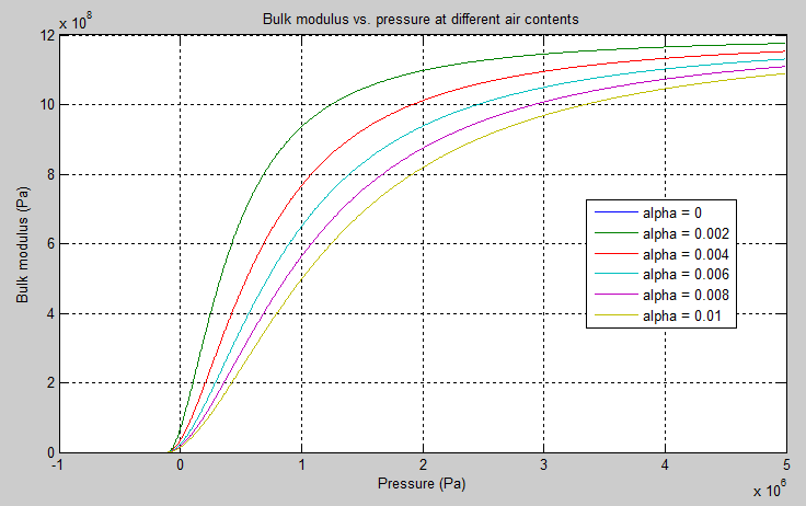
To reproduce this graph, copy and paste the following script in your MATLAB® Command Window:
% Parameters
p_atm    = 1.01325e5;            % Atmospheric pressure [Pa]
pressure = -1.01325e5:1e3:5e6;   % Pressure (gauge) [Pa]
alpha    = 0:2e-3:0.01;          % Relative amount of trapped air
k_sh     = 1.4;                  % Specific heat ratio
bulk     = 1.24285e+09;          % Bulk modulus at atmospheric pressure and no gas [Pa]

% Absolute pressure
p_abs = p_atm + pressure;
% Relative absolute pressure
p_nom = (p_atm./p_abs).^(1/k_sh);
p_den = p_nom .* bulk ./ (k_sh .* p_abs);
% Instantaneous bulk modulus
bulk_inst = bulk * (1+ bsxfun(@times, alpha', p_nom)) ./ (1 + bsxfun(@times, alpha', p_den));

% Reuse figure if it exists, else create new figure
if ~exist('h1_bulk_modulus', 'var') || ~isgraphics(h1_bulk_modulus, 'figure')
    h1_bulk_modulus = figure('Name', 'h1_bulk_modulus');
end
figure(h1_bulk_modulus)
clf(h1_bulk_modulus)
legend_label = cell(length(alpha),1);

for i=1:length(alpha)
    plot(pressure, bulk_inst(i,:))
    hold on
    legend_label{i,1} = ['alpha = ',num2str(alpha(i))];
end

grid on
xlabel('Pressure (Pa)')
ylabel('Bulk modulus (Pa)')
title('Bulk modulus vs. pressure at different air contents')
legend(legend_label, 'Location', 'Best')
hold off
Cavitation is an inherently thermodynamic process, requiring consideration of multiple-phase fluids, heat transfers, etc., and as such cannot be accurately simulated with Simscape™ software. But the simplified version implemented in the block is good enough to signal if pressure falls below dangerous level, and to prevent computation failure that normally occurs at negative pressures.
If pressure falls below absolute vacuum (–101325 Pa), the simulation stops and an error message is displayed.
If chamber walls have noticeable compliance, the above equations must be further enhanced by representing geometrical chamber volume as a function of pressure:
where
| d | Internal diameter of the cylindrical chamber |
| L | Length of the cylindrical chamber |
| Kp | Proportionality coefficient (m/Pa) |
| τ | Time constant |
| s | Laplace operator |
Coefficient Kp establishes
relationship between pressure and the internal diameter at steady-state conditions. For
metal tubes, the coefficient can be computed as (see [2]):
where
| D | Pipe external diameter |
| EM | Modulus of elasticity (Young's modulus) for the pipe material |
| ν | Poisson's ratio for the pipe material |
For hoses, the coefficient can be provided by the manufacturer.
The process of expansion and contraction in pipes and especially in hoses is a complex combination of nonlinear elastic and viscoelastic deformations. This process is approximated in the block with the first-order lag, whose time constant is determined empirically (for example, see [3]).
As a result, by selecting appropriate values, you can implement four different models of fluid compressibility with this block:
Chamber with rigid walls, no entrained gas in the fluid
Cylindrical chamber with compliant walls, no entrained gas in the fluid
Chamber with rigid walls, fluid with entrained gas
Cylindrical chamber with compliant walls, fluid with entrained gas
The block allows two methods of specifying the chamber size:
By volume — Use this option for cylindrical or non-cylindrical chambers with rigid walls. You only need to know the volume of the chamber. This chamber type does not account for wall compliance.
By length and diameter — Use this option for cylindrical chambers with rigid or compliant walls, such as circular pipes or hoses.
The block has one hydraulic conserving port associated with the chamber inlet. The block positive direction is from its port to the reference point. This means that the flow rate is positive if it flows into the chamber.
Variables
To set the priority and initial target values for the block variables prior to simulation, use the Initial Targets section in the block dialog box or Property Inspector. For more information, see Set Priority and Initial Target for Block Variables.
Nominal values provide a way to specify the expected magnitude of a variable in a model. Using system scaling based on nominal values increases the simulation robustness. Nominal values can come from different sources, one of which is the Nominal Values section in the block dialog box or Property Inspector. For more information, see Modify Nominal Values for a Block Variable.
Basic Assumptions and Limitations
No inertia associated with pipe walls is taken into account.
Chamber with compliant walls is assumed to have a cylindrical shape. Chamber with rigid wall can have any shape.
Parameters
- Chamber specification
The parameter can have one of two values:
By volumeorBy length and diameter. The valueBy length and diameteris recommended if a chamber is formed by a circular pipe. If the parameter is set toBy volume, wall compliance is not taken into account. The default value of the parameter isBy volume.- Chamber wall type
The parameter can have one of two values:
Rigid wallorFlexible wall. If the parameter is set toRigid wall, wall compliance is not taken into account, which can improve computational efficiency. The valueFlexible wallis recommended for hoses and metal pipes, where compliance can affect the system behavior. The default value of the parameter isRigid wall. The parameter is used if the Chamber specification parameter is set toBy length and diameter.- Chamber volume
Volume of fluid in the chamber. The default value is
1e-4m^3. The parameter is used if the Chamber specification parameter is set toBy volume.- Chamber internal diameter
Internal diameter of the cylindrical chamber. The default value is
0.01m. The parameter is used if the Chamber specification parameter is set toBy length and diameter.- Cylindrical chamber length
Length of the cylindrical chamber. The default value is
1m. The parameter is used if the Chamber specification parameter is set toBy length and diameter.- Static pressure-diameter coefficient
Coefficient
Kpthat establishes relationship between pressure and the internal diameter at steady-state conditions. The parameter can be determined analytically or experimentally. The default value is1.2e-12m/Pa. The parameter is used if Chamber wall type is set toFlexible wall.- Viscoelastic process time constant
Time constant in the transfer function relating pipe internal diameter to pressure variations. With this parameter, the simulated elastic or viscoelastic process is approximated with the first-order lag. The parameter is determined experimentally or provided by the manufacturer. The default value is
0.01s. The parameter is used if Chamber wall type is set toFlexible wall.- Specific heat ratio
Gas-specific heat ratio. The default value is
1.4.
Global Parameters
Parameters determined by the type of working fluid:
Fluid bulk modulus
Nondissolved gas ratio — Nondissolved gas relative content determined as a ratio of gas volume to the liquid volume.
Use the Hydraulic Fluid (Simscape Fluids) block or the Custom Hydraulic Fluid block to specify the fluid properties.
Ports
The block has one hydraulic conserving port associated with the chamber inlet.
References
[1] Manring, N.D., Hydraulic Control Systems, John Wiley & Sons, New York, 2005
[2] Meritt, H.E., Hydraulic Control Systems, John Wiley & Sons, New York, 1967
[3] Holcke, Jan, Frequency Response of Hydraulic Hoses, RIT, FTH, Stockholm, 2002
Extended Capabilities
Version History
Introduced in R2009bSee Also
You can also select a web site from the following list:
Americas
- América Latina (Español)
- Canada (English)
- United States (English)
Europe
- Belgium (English)
- Denmark (English)
- Deutschland (Deutsch)
- España (Español)
- Finland (English)
- France (Français)
- Ireland (English)
- Italia (Italiano)
- Luxembourg (English)
- Netherlands (English)
- Norway (English)
- Österreich (Deutsch)
- Portugal (English)
- Sweden (English)
- Switzerland
- United Kingdom (English)